
Skadi 6 bay


About the Skadi 6 bay PCB
Skadi 6 bay is an open source STM32 PCB design by M0RCHED, published on GitHub under the Apache-2.0 license. It is a 2-layer board, with 106 components from 51 distinct parts.
Its main chip is the STM32F103C8Tx, from the STM32 family. Other key parts include the PCA9634PW, TPS562200, TCA9803, USBLC6-2SC6 and TCA9548APWR. By type, the board carries 32 resistors, 28 capacitors, 14 test points, 12 diodes, 6 ICs and 5 connectors.
It belongs with the power & battery designs in this gallery.
From the project
Les transporteurs internationaux (UPS, FedEx, DHL, etc.) n'acceptent pas l'expédition de batteries Li-ion > 30 % SoC en raison des risques thermiques.
Les transporteurs internationaux (UPS, FedEx, DHL, etc.) n'acceptent pas l'expédition de batteries Li-ion > 30 % SoC en raison des risques thermiques.
Le Skadi 6-Bay Smart Charger permet de ramener automatiquement chaque batterie au seuil de ~30 % SoC, qu'elle soit initialement trop basse (charge) ou trop haute (décharge via ELOAD externe).
- ✅ 6 baies indépendantes avec contrôle charge/décharge par MOSFET - ✅ Supervision I²C via multiplexeur TCA9548A + répéteurs TCA9803 - ✅ Fuel gauge MAX17263 intégré dans chaque pack (SoC, température, tension) - ✅ Machine à états finie (FSM) avec…

Main components on the Skadi 6 bay
Skadi 6 bay bill of materials (BOM)
106 components, 51 distinct parts.
| Qty | Part | Footprint | Refs |
|---|---|---|---|
| 1 | PCA9634PW | SOP65P640X110-20N | IC1 |
| 1 | TPS562200 | SOT-23-6 | U1 |
| 1 | TCA9803 | VSSOP-8_3x3mm_P0.65mm | U2 |
| 1 | USBLC6-2SC6 | SOT-23-6 | U3 |
| 1 | STM32F103C8Tx | LQFP-48_7x7mm_P0.5mm | U4 |
| 1 | TCA9548APWR | TSSOP-24_4.4x7.8mm_P0.65mm | U6 |
| 1 | Fan | M1 | |
| 1 | 16MHz | Y1 | |
| 1 | PWR_IN | PhoenixContact_SPT_2.5_2-H-5.0_1x02_P5.0mm_Horizontal | J1 |
| 1 | Conn_01x04_Socket | PinSocket_1x04_P2.54mm_Vertical | J3 |
| 1 | ELOAD | TerminalBlock_Phoenix_MKDS-1,5-2-5.08_1x02_P5.08mm_Horizontal | J4 |
| 1 | Screw_Terminal_01x02 | J5 | |
| 1 | USB_C_Plug_USB2.0 | P1 | |
| 1 | 12A fast | F1 | |
| 2 | AO4407A | SOIC127P600X175-8N | Q_CHG1, Q_DIS2 |
| 2 | DMG2302U | SOT-23 | Q_CHG_DRV1, Q_DIS_DRV2 |
| 1 | TP_DIS_GATE | TP1 | |
| 1 | TP_CHG_GATE | TP2 | |
| 12 | TestPoint | TestPoint_Pad_D2.3mm | TP6, TP7, TP8, TP9, TP10, TP11, TP12, TP13 +4 |
| 1 | TVS | D_SMA | D1 |
Show 31 more
| Qty | Part | Footprint | Refs |
|---|---|---|---|
| 2 | 1N4148WT | D_SOD-523 | D2, D11 |
| 9 | LED | D3, D4, D5, D6, D7, D8, D9, D10 +1 | |
| 1 | 120R | L_0603_1608Metric | FB1 |
| 1 | 3.3 uH | L1 | |
| 1 | 470 µF / 25 V | CP_Elec_8x10.5 | C1 |
| 1 | 470 µF / 25 V | C_1206_3216Metric | C2 |
| 5 | 100 nF | C3, C4, C6, C7, C12 | |
| 2 | 10 uF | C5, C10 | |
| 2 | 22 uF | C8, C9 | |
| 1 | 4.7 nF | C11 | |
| 5 | 100nF | C_0402_1005Metric | C13, C14, C15, C23, C24 |
| 1 | 10uF | C_0805_2012Metric | C16 |
| 1 | 10nF | C_0402_1005Metric | C17 |
| 2 | 1uF | C_0805_2012Metric | C18, C19 |
| 2 | 100nF | C20, C21 | |
| 1 | 1uF | C22 | |
| 2 | 10pF | C25, C26 | |
| 1 | 4.7uF | C27 | |
| 1 | 10uF | C28 | |
| 2 | 33K | R1, R13 | |
| 5 | 10K | R2, R3, R7, R28, R29 | |
| 1 | 200R | R4 | |
| 5 | 100K | R5, R12, R22, R25, R27 | |
| 2 | 1K | R6, R23 | |
| 2 | 2K2 | R8, R9 | |
| 1 | 47k | R_0603_1608Metric | R10 |
| 1 | 10k | R_0603_1608Metric | R11 |
| 8 | 680R | R14, R15, R16, R17, R18, R19, R20, R21 | |
| 2 | 100R | R24, R26 | |
| 1 | R | R30 | |
| 2 | 22R | R31, R32 |
Skadi 6 bay design files
The KiCad project lives in the M0RCHED/skadi_6_bay repository on GitHub; these links point at the commit this page was built from.
Skadi 6 bay: common questions
What microcontroller does the Skadi 6 bay use?
The Skadi 6 bay is built around the STM32F103C8Tx, from the STM32 family.
How big is the Skadi 6 bay PCB?
The Skadi 6 bay has 2 copper layers and is 1.6 mm thick.
How many components are on the Skadi 6 bay?
106 components, from 51 distinct parts. The full bill of materials is listed on this page.
Where can I download the Skadi 6 bay design files?
From the M0RCHED/skadi_6_bay repository on GitHub, which has the KiCad layout and the schematic; the links under Design files point to each one.
Can I use the Skadi 6 bay design in my own project?
Yes, under the terms of its Apache-2.0 license, which M0RCHED chose for the repository.
Can I test firmware for the Skadi 6 bay without the hardware?
Yes. HardLabs builds a simulation of the board from its netlist and BOM, so you can run and debug STM32 firmware against it before you order a PCB.
Similar boards
 STM32
STM32LumenPnP Motherboard
opulo-inc
149 × 95 mm296 parts4LCC-BY-SA-4.03.7k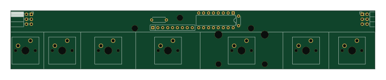 STM32
STM32Type c
google
188 × 30 mm17 parts2LApache-2.02.9k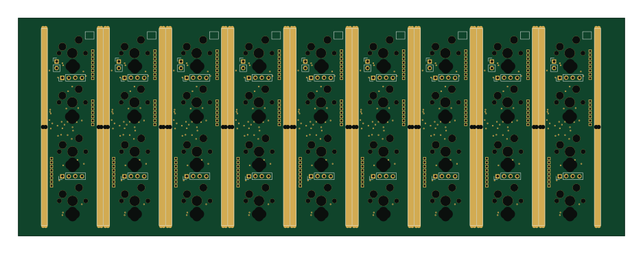 STM32
STM32Main panel
234 × 84 mm26 parts4LApache-2.02.9k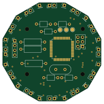 STM32
STM32Base
52.3 × 52.3 mm36 parts2LApache-2.02.9k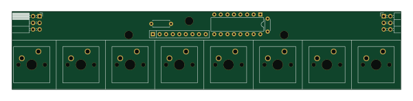 STM32
STM32Type a
150 × 30 mm14 parts2LApache-2.02.9k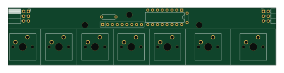 STM32
STM32Type e
140.5 × 30 mm13 parts2LApache-2.02.9k