
LinHT-rf amp

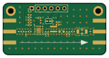
About the LinHT-rf amp PCB
LinHT-rf amp is an open source PCB design by M17-Project, published on GitHub under the CC-BY-NC-4.0 license. It is a 4-layer board measuring 40 × 20 mm, with 21 components from 18 distinct parts.
Other key parts include the GRF5604. By type, the board carries 12 capacitors, 4 inductors, 3 resistors and 1 IC.
It belongs with the audio designs in this gallery.
From the project
Test board for the Guerrilla RF GRF5604 RF amplifier integrated circuit
Standalone RF power amplifier module for the LinHT handheld, built around the Guerrilla RF GRF5604. This repository houses a proof-of-concept (PoC) board used to evaluate matching, biasing, efficiency, and linearity in the 420–450 MHz band. Results from this effort will feed back into, and eventually be integrated with the main LinHT hardware project.
- Design tested - works. - Tuning follows the vendor's reference design for 397–470 MHz
Main components on the LinHT-rf amp
LinHT-rf amp bill of materials (BOM)
21 components, 18 distinct parts.
| Qty | Part | Footprint | Refs |
|---|---|---|---|
| 1 | GRF5604 | QFN-16-1EP_3x3mm_P0.5mm_EP1.7x1.7mm_ThermalVias | U1 |
| 1 | LFCN-490 | Filter_Mini-Circuits_FV1206 | FL1 |
| 1 | 20nH | L_0402_1005Metric | L1 |
| 1 | 23nH | 0908SQ-23N | L2 |
| 1 | 2.4nH | L_0603_1608Metric | L3 |
| 1 | 10n | L_0402_1005Metric | L4 |
| 3 | 1n | C_0402_1005Metric | C1, C2, C4 |
| 1 | 100n | C_0402_1005Metric | C3 |
| 1 | 10u | C_0402_1005Metric | C5 |
| 1 | 10p | C_0402_1005Metric | C6 |
| 2 | 33p | C_0402_1005Metric | C7, C9 |
| 1 | 100p | C_0402_1005Metric | C8 |
| 1 | 6p8 | C_0402_1005Metric | C10 |
| 1 | 27p | C_0402_1005Metric | C11 |
| 1 | 3p | C_0402_1005Metric | C12 |
| 1 | 100k | R_0402_1005Metric | R1 |
| 1 | 1k96 | R_0402_1005Metric | R2 |
| 1 | 6k04 | R_0402_1005Metric | R3 |
LinHT-rf amp design files
The KiCad project lives in the M17-Project/LinHT-rf-amp repository on GitHub; these links point at the commit this page was built from.
- LayoutLinHT-rf-amp.kicad_pcb
- SchematicLinHT-rf-amp.kicad_sch
LinHT-rf amp: common questions
How big is the LinHT-rf amp PCB?
The LinHT-rf amp measures 40 × 20 mm, has 4 copper layers and is 0.982 mm thick.
How many components are on the LinHT-rf amp?
21 components, from 18 distinct parts. The full bill of materials is listed on this page.
Where can I download the LinHT-rf amp design files?
From the M17-Project/LinHT-rf-amp repository on GitHub, which has the KiCad layout and the schematic; the links under Design files point to each one.
Can I use the LinHT-rf amp design in my own project?
It is published under CC-BY-NC-4.0, which limits how it may be reused; read the license before building on it.
Similar boards
KLOR
GEIGEIGEIST
160.2 × 118.3 mm79 parts2LGPL-3.01.2k
USB
shanteacontrols
52 × 12.6 mm6 parts2LApache-2.0956
Pots
390 × 93 mm75 parts2LApache-2.0956
ButtonsLEDs
390 × 37 mm82 parts2LApache-2.0956
PicoGUS Hand386
polpo
29.2 × 75.2 mm43 parts4LGPL-2.0800
Snark barker
schlae
231.1 × 106.7 mm193 parts2LNo license687