
Azaltma

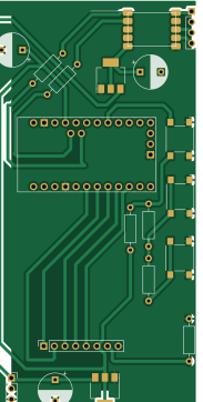
About the Azaltma PCB
Azaltma is an open source PCB design by mahmut26, published on GitHub. It is a 2-layer board measuring 43 × 90.5 mm, with 19 components from 9 distinct parts.
Other key parts include the AMS1117-5.0, AMS1117-3.3 and Clone_Pro_Mini_Socket_NoSPH. By type, the board carries 6 resistors, 3 ICs, 3 connectors, 3 switches, 3 capacitors and 1 module.
It belongs with the rf & radio designs in this gallery.
Main components on the Azaltma
Azaltma bill of materials (BOM)
19 components, 9 distinct parts.
| Qty | Part | Footprint | Refs |
|---|---|---|---|
| 1 | ~ | rda | U1 |
| 1 | AMS1117-5.0 | SOT-223-3_TabPin2 | U2 |
| 1 | AMS1117-3.3 | SOT-223-3_TabPin2 | U3 |
| 1 | Clone_Pro_Mini_Socket_NoSPH | Clone_Pro_Mini_Socket_NoSPH | A1 |
| 2 | Conn_01x04_Socket | PinSocket_1x04_P2.54mm_Vertical | J1, J2 |
| 1 | Conn_01x08_Pin | PinSocket_1x08_P2.54mm_Vertical | J3 |
| 3 | SW_Push | SW_SPST_Omron_B3FS-100xP | SW1, SW2, SW3 |
| 3 | C | CP_Radial_D8.0mm_P5.00mm | C2, C3, C4 |
| 6 | R | R_Axial_DIN0207_L6.3mm_D2.5mm_P10.16mm_Horizontal | R1, R2, R3, R4, R5, R6 |
Azaltma design files
The KiCad project lives in the mahmut26/Radio_PCB_ARDUINO repository on GitHub; these links point at the commit this page was built from.
- LayoutSmaller/azaltma.kicad_pcb
- SchematicSmaller/azaltma.kicad_sch
Azaltma: common questions
How big is the Azaltma PCB?
The Azaltma measures 43 × 90.5 mm, has 2 copper layers and is 1.6 mm thick.
How many components are on the Azaltma?
19 components, from 9 distinct parts. The full bill of materials is listed on this page.
Where can I download the Azaltma design files?
From the mahmut26/Radio_PCB_ARDUINO repository on GitHub, which has the KiCad layout and the schematic; the links under Design files point to each one.
Can I use the Azaltma design in my own project?
The repository has no license, so all rights stay with mahmut26. Use it as a reference, and ask the author before reusing the design.
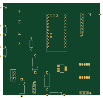
More boards in Radio_PCB_ARDUINO
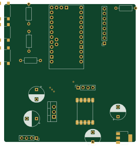
Similar boards
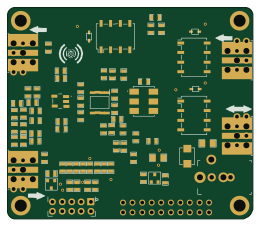
Hat
pa3gsb
65 × 56 mm81 parts2LNo license675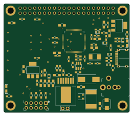
Radioberry juice
65 × 56 mm87 parts2LNo license675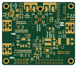
Radioberry preamp
65 × 56 mm137 parts2LNo license675
Goodwatch20
travisgoodspeed
25.6 × 27.6 mm20 parts2LNo license568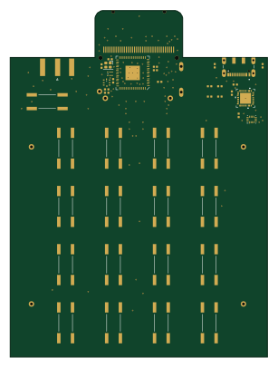
GoodPocketWatch
75.2 × 101.2 mm56 parts2LNo license568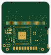
Goodwatch31
25.6 × 27.6 mm23 parts2LNo license568