
Doorbot lcd

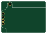
About the Doorbot lcd PCB
Doorbot lcd is an open source PCB design by makeitlabs, published on GitHub. It is a 2-layer board measuring 40.1 × 28.5 mm, with 5 components from 4 distinct parts.
It belongs with the displays & leds and dev boards & breakouts designs in this gallery.
From the project
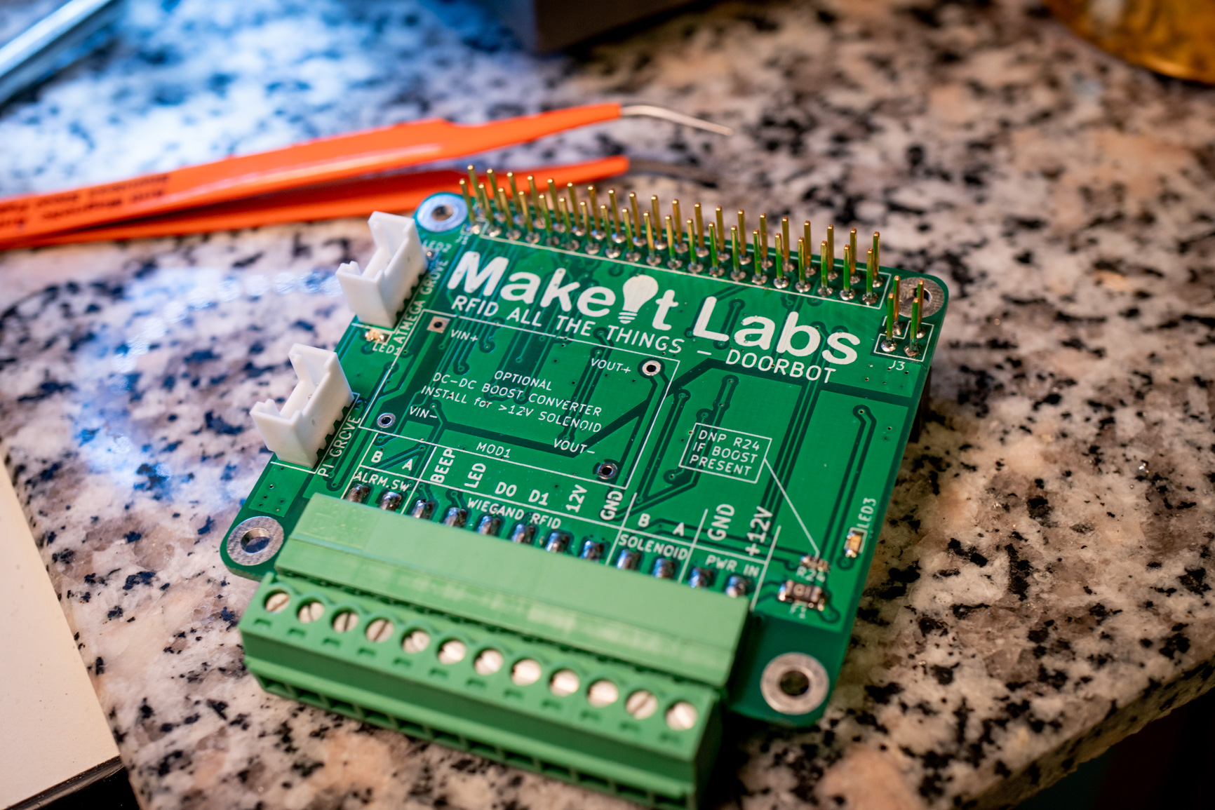
Doorbot is an RFID access control platform, primarily intended for exterior doors in a makerspace environment. Based on Raspberry Pi 3b+, PoE hat, and a custom interface hat.
- pihat - Access control hat that sandwiches between a Raspberry Pi 3b+ and a Raspberry Pi PoE hat. It provides isolated Wiegand RFID reader translation as well as isolated PWM solenoid control. - i2clcd - Presently incomplete project for an I2C add-on display for the Doorbot Pi hat.
Doorbot lcd bill of materials (BOM)
5 components, 4 distinct parts.
| Qty | Part | Footprint | Refs |
|---|---|---|---|
| 1 | NHD-C0220BiZ-FS(RGB)-FBW-3VM | NHD-C0220BiZ-FS(RGB)-FBW-3VM | LCD1 |
| 1 | 2.2uF | C_0805_2012Metric | C1 |
| 2 | 1uF | C_0603_1608Metric | C2, C3 |
| 1 | .1uF | C_0603_1608Metric | C4 |
Doorbot lcd design files
The KiCad project lives in the makeitlabs/doorbot repository on GitHub; these links point at the commit this page was built from.
Doorbot lcd: common questions
How big is the Doorbot lcd PCB?
The Doorbot lcd measures 40.1 × 28.5 mm, has 2 copper layers and is 1.6 mm thick.
How many components are on the Doorbot lcd?
5 components, from 4 distinct parts. The full bill of materials is listed on this page.
Where can I download the Doorbot lcd design files?
From the makeitlabs/doorbot repository on GitHub, which has the KiCad layout; the links under Design files point to each one.
Can I use the Doorbot lcd design in my own project?
The repository has no license, so all rights stay with makeitlabs. Use it as a reference, and ask the author before reusing the design.
More boards in doorbot
Similar boards

LevelShifterBreakout
scottbez1
15.2 × 20.3 mm5 parts2LApache-2.022.2k
View base
81.2 × 81.2 mm81 parts2LApache-2.022.2k
View screen
35 × 35 mm12 parts2LApache-2.022.2k
BM28B0.6-24DSBreakout
15.2 × 35.6 mm3 parts2LApache-2.022.2k
ChainlinkDriverTester
198.1 × 95.3 mm123 parts2LApache-2.04.2k
ChainlinkBase
98.4 × 190.5 mm119 parts2LApache-2.04.2k