
LPC1114-LCD

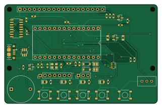
About the LPC1114-LCD PCB
LPC1114-LCD is an open source NXP PCB design by MarceloSalazar, published on GitHub under the MIT license. It is a 2-layer board measuring 80 × 52 mm, with 53 components from 34 distinct parts.
Its main chip is the NXP LPC1114FN28/102 + DIP-28 600mil socket, from the NXP family. Other key parts include the Torex XC6206P332MR-G, WCH CH340C (SOIC-16, no crystal), Analog Devices DS3231MZ+ (+-5ppm MEMS RTC) and ST USBLC6-2SC6. By type, the board carries 17 resistors, 10 capacitors, 6 diodes, 5 ICs, 5 switches and 3 connectors.
It belongs with the displays & leds designs in this gallery.
From the project
Las librerías del proyecto se referencian con ${KIPRJMOD} en sym-lib-table y fp-lib-table, así que el proyecto se abre directamente sin configurar nada. El resto de símbolos, footprints y modelos 3D son los estándar de KiCad 10.
Las librerías del proyecto se referencian con ${KIPRJMOD} en sym-lib-table y fp-lib-table, así que el proyecto se abre directamente sin configurar nada. El resto de símbolos, footprints y modelos 3D son los estándar de KiCad 10.
1. Edita el esquemático y el PCB en KiCad. 2. En el PCB: Herramientas → Actualizar PCB desde el esquemático (F8) y vuelve a rellenar las zonas (B). 3. Ejecuta el script desde la raíz del repositorio:
Main components on the LPC1114-LCD
LPC1114-LCD bill of materials (BOM)
53 components, 34 distinct parts — part numbers from the project's BOM.
| Qty | Part | Footprint | Refs |
|---|---|---|---|
| 1 | NXP LPC1114FN28/102 + DIP-28 600mil socket LPC1114FN28/102 | DIP-28_W15.24mm_Socket | U1 |
| 1 | Torex XC6206P332MR-G XC6206P332MR-G | SOT-23 | U2 |
| 1 | WCH CH340C (SOIC-16, no crystal) CH340C | SOIC-16_3.9x9.9mm_P1.27mm | U3 |
| 1 | Analog Devices DS3231MZ+ (+-5ppm MEMS RTC) DS3231MZ+ | SOIC-8_3.9x4.9mm_P1.27mm | U4 |
| 1 | ST USBLC6-2SC6 USBLC6-2SC6 | SOT-23-6_Handsoldering | U5 |
| 2 | SS8050 | SOT-23 | Q1, Q2 |
| 1 | YXC X322512MSB4SI 12MHz CL=20pF 12MHz | Crystal_SMD_3225-4Pin_3.2x2.5mm | Y1 |
| 1 | XKB U254-051T-4BH83-F1S USB_B_Micro | USB_Micro-B_XKB_U254-051T-4BH83-F1S | J1 |
| 1 | SWD+I2C | PinHeader_1x07_P2.54mm_Vertical | J2 |
| 1 | UART | PinHeader_1x03_P2.54mm_Vertical | J3 |
| 1 | Keystone 3034 (SMD CR2032 holder) CR2032 | BatteryHolder_Keystone_3034_1x20mm | BT1 |
| 1 | TDK PS1420P02CT (piezo, D14 mm, pitch 10 mm) PS1420P02CT | Buzzer_TDK_PS1420P02CT_D14mm_P10mm | BZ1 |
| 1 | LCD1602 (HD44780/ST7066) | LCD1602_18pin | DS1 |
| 1 | 10K 10k | Potentiometer_Bourns_3296W_Vertical | RV1 |
| 1 | C318884 MODE/ISP | SW_TS-1187A_5.1x5.1mm | SW1 |
| 1 | C318884 UP | SW_TS-1187A_5.1x5.1mm | SW2 |
| 1 | C318884 DOWN | SW_TS-1187A_5.1x5.1mm | SW3 |
| 1 | C318884 OK | SW_TS-1187A_5.1x5.1mm | SW4 |
| 1 | C318884 RESET | SW_TS-1187A_5.1x5.1mm | SW5 |
| 1 | C84256 Red | LED_0805_2012Metric | D1 |
Show 14 more
| Qty | Part | Footprint | Refs |
|---|---|---|---|
| 1 | C2296 Yellow | LED_0805_2012Metric | D2 |
| 1 | C2297 Green | LED_0805_2012Metric | D3 |
| 1 | C2297 Green (PWR) | LED_0805_2012Metric | D4 |
| 2 | B5819W | D_SOD-123 | D6, D7 |
| 2 | 10UF 10uF | C_0805_2012Metric | C1, C2 |
| 5 | 100NF 100nF | C_0603_1608Metric | C3, C4, C7, C8, C10 |
| 2 | 33PF 33pF | C_0603_1608Metric | C5, C6 |
| 1 | 100nF | C_0603_1608Metric | C9 |
| 3 | 10K 10k | R_0603_1608Metric | R1, R13, R15 |
| 5 | 1k | R_0603_1608Metric | R2, R8, R12, R14, R16 |
| 2 | 4K7 4k7 | R_0603_1608Metric | R3, R4 |
| 3 | 470 | R_0603_1608Metric | R5, R6, R7 |
| 3 | 100 | R_0603_1608Metric | R9, R10, R11 |
| 1 | 10K 10k | R_Array_Convex_4x0603 | RN2 |
LPC1114-LCD design files
The KiCad project lives in the MarceloSalazar/LPC1114-LCD repository on GitHub; these links point at the commit this page was built from.
LPC1114-LCD: common questions
What microcontroller does the LPC1114-LCD use?
The LPC1114-LCD is built around the NXP LPC1114FN28/102 + DIP-28 600mil socket, from the NXP family.
How big is the LPC1114-LCD PCB?
The LPC1114-LCD measures 80 × 52 mm, has 2 copper layers and is 1.6 mm thick.
How many components are on the LPC1114-LCD?
53 components, from 34 distinct parts, with part numbers taken from the project's own BOM. The full bill of materials is listed on this page.
Where can I download the LPC1114-LCD design files?
From the MarceloSalazar/LPC1114-LCD repository on GitHub, which has the KiCad layout, the schematic and the BOM; the links under Design files point to each one.
Can I use the LPC1114-LCD design in my own project?
Yes, under the terms of its MIT license, which MarceloSalazar chose for the repository.
Can I test firmware for the LPC1114-LCD without the hardware?
Yes. HardLabs builds a simulation of the board from its netlist and BOM, so you can run and debug NXP firmware against it before you order a PCB.
Similar boards
 NXP
NXP32Bit shift register
MaltWhiskey
100 × 54 mm56 parts4LNo license763 NXP
NXPMega-Cube-Board
200 × 54 mm100 parts4LNo license763 NXP
NXPMCL64
MicroCoreLabs
39.3 × 61.8 mm9 parts4LNo license532 NXP
NXPROM Emulator
21.5 × 37.1 mm5 parts2LNo license532 NXP
NXPMCLZ8
37.1 × 61.5 mm6 parts4LNo license532 NXP
NXPXTMAX
81 × 46 mm14 parts4LNo license532