
Booster-Shield

About the Booster-Shield
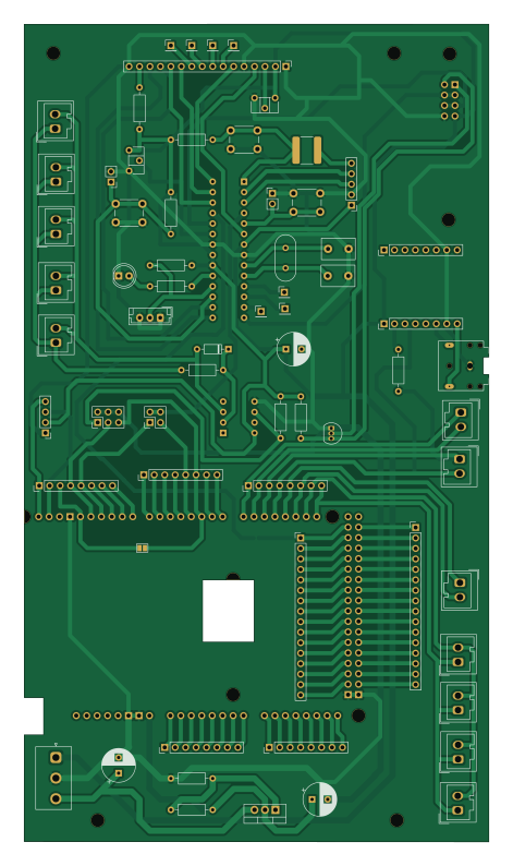
Booster-Shield is an open source AVR/Arduino PCB design by martinfantini, published on GitHub. It is a 2-layer board measuring 112.7 × 198.2 mm, with 71 components from 37 distinct parts.
Its main chip is the ATmega328-P, from the AVR/Arduino family. Other key parts include the LD1086V-DG. By type, the board carries 15 connectors, 2 jumpers, 1 IC and 1 LED.
It belongs with the dev boards & breakouts designs in this gallery.
From the project
This repo contains all the information regarding to the model trains project
As a DCC central, I use the open source project CommandStation-EX, here is added as asubmodule up this project. Usigin Arduino ATMega 328, I generate a booster with the use of the motor diver BTS7960
Here is the CommandStation-EX project used to generate the DCC central, which will be user to control all the trains and diferent periferics asociated to the DCC protocol.
Main components on the Booster-Shield
Booster-Shield bill of materials (BOM)
71 components, 37 distinct parts.
| Qty | Part | Footprint | Refs |
|---|---|---|---|
| 1 | LD1086V-DG | TO-220-3_Vertical | U2 |
| 5 | Conn_01x08 | PinHeader_1x08_P2.54mm_Vertical | J1, J2, J3, J4, J5 |
| 7 | Conn_01x01 | PinHeader_1x01_P2.54mm_Vertical | J6, J7, J8, J9, J10, J11, J12 |
| 1 | Conn_01x04 | PinHeader_1x04_P2.54mm_Vertical | J13 |
| 2 | Conn_01x02_Pin | PinHeader_1x02_P2.54mm_Vertical | J14, J16 |
| 1 | ATmega328-P | DIP-28_W7.62mm | Arduino_1 |
| 1 | AudioJack3 | Jack_3.5mm_CUI_SJ1-3523N_Horizontal | AudioOutput1 |
| 2 | 10uF | CP_Radial_D8.0mm_P3.80mm | C_Ard_In2, C_Ard_Out2 |
| 1 | 47uF | CP_Radial_D8.0mm_P3.80mm | C_Filter_1 |
| 1 | 100nF | C_2225_5664Metric_Pad1.80x6.60mm_HandSolder | C_Rest1 |
| 2 | 22 pF | C_Disc_D8.0mm_W5.0mm_P5.00mm | C_XTAL_1, C_XTAL_2 |
| 1 | Arduino_Mega2560_Shield | Arduino_Mega2560_Shield | Central2 |
| 3 | Conn_01x16 | PinHeader_1x16_P2.54mm_Vertical | Con_Ard_1, Con_Ard_5, Disp_Conn1 |
| 1 | Debuger | PinHeader_1x05_P2.54mm_Vertical | Conn_Debuger_1 |
| 1 | Conn_02x02_Odd_Even | PinHeader_2x02_P2.54mm_Vertical | DCC_Enable_Sig_1 |
| 5 | DCC | Wago_734-132_1x02_P3.50mm_Vertical | DCC_In1, DCC_In2, DCC_In3, DCC_In4, DCC_In5 |
| 1 | Conn_02x03_Odd_Even | PinHeader_2x03_P2.54mm_Vertical | DCC_Select_1 |
| 2 | Conn_01x08_Pin | PinHeader_1x08_P2.54mm_Vertical | DPF_Left1, DPF_Right1 |
| 1 | 1N4148 | D_DO-35_SOD27_P7.62mm_Horizontal | D_SGN_1 |
| 4 | I2C | Wago_734-132_1x02_P3.50mm_Vertical | I2C_1, I2C_2, I2C_3, I2C_4 |
Show 17 more
| Qty | Part | Footprint | Refs |
|---|---|---|---|
| 1 | Conn_01x03_Female | JST_NV_B03P-NV_1x03_P5.00mm_Vertical | Input1 |
| 2 | Jumper_2_Open | SolderJumper-2_P1.3mm_Open_Pad1.0x1.5mm | JP1, JP2 |
| 1 | Conn_01x08_Female | PinHeader_2x04_P2.54mm_Vertical | J_Booster_Connector1 |
| 1 | 6N136 | DIP-8_W7.62mm | O_SGN_DCC1 |
| 1 | 2N7000 | TO-92_Inline | Q_Inverter1 |
| 1 | R_Pot_Bck_Light | Potentiometer_ACP_CA6-H2,5_Horizontal | RV1 |
| 1 | R_Pot_Curr | Potentiometer_ACP_CA6-H2,5_Horizontal | RV2 |
| 1 | 3K9 | R_Axial_DIN0207_L6.3mm_D2.5mm_P10.16mm_Horizontal | R_Ard_3 |
| 1 | 560 | R_Axial_DIN0207_L6.3mm_D2.5mm_P10.16mm_Horizontal | R_Ard_4 |
| 3 | 1K | R_Axial_DIN0207_L6.3mm_D2.5mm_P10.16mm_Horizontal | R_Audio1, R_Pull_Up_2, R_SGN_1 |
| 1 | 135 | R_Axial_DIN0207_L6.3mm_D2.5mm_P10.16mm_Horizontal | R_Back_Led1 |
| 5 | 10K | R_Axial_DIN0207_L6.3mm_D2.5mm_P10.16mm_Horizontal | R_Continue1, R_Led1, R_Pull_Up_1, R_Pull_Up_3, R_Reset1 |
| 3 | SW_DIP_x01 | SW_PUSH_6mm_H5mm | SW_Continue1, SW_Interruption1, SW_reset1 |
| 3 | Serial | Wago_734-132_1x02_P3.50mm_Vertical | Serial_1, Serial_2, Serial_3 |
| 1 | Conn_01x03_Female | JST_EH_B3B-EH-A_1x03_P2.50mm_Vertical | Temperature_Sensor1 |
| 1 | Crystal 16 Mhz | Crystal_HC49-U_Vertical | XTAL1 |
| 1 | CQY99 | LED_D5.0mm_IRGrey | Led1 |
Booster-Shield design files
The KiCad project lives in the martinfantini/ModelTrains repository on GitHub; these links point at the commit this page was built from.
Booster-Shield: common questions
What microcontroller does the Booster-Shield use?
The Booster-Shield is built around the ATmega328-P, from the AVR/Arduino family.
How big is the Booster-Shield?
The Booster-Shield measures 112.7 × 198.2 mm, has 2 copper layers and is 1.6 mm thick.
How many components are on the Booster-Shield?
71 components, from 37 distinct parts. The full bill of materials is listed on this page.
Where can I download the Booster-Shield design files?
From the martinfantini/ModelTrains repository on GitHub, which has the KiCad layout and the schematic; the links under Design files point to each one.
Can I use the Booster-Shield design in my own project?
The repository has no license, so all rights stay with martinfantini. Use it as a reference, and ask the author before reusing the design.
Can I test firmware for the Booster-Shield without the hardware?
Yes. HardLabs builds a simulation of the board from its netlist and BOM, so you can run and debug AVR/Arduino firmware against it before you order a PCB.
More boards in ModelTrains
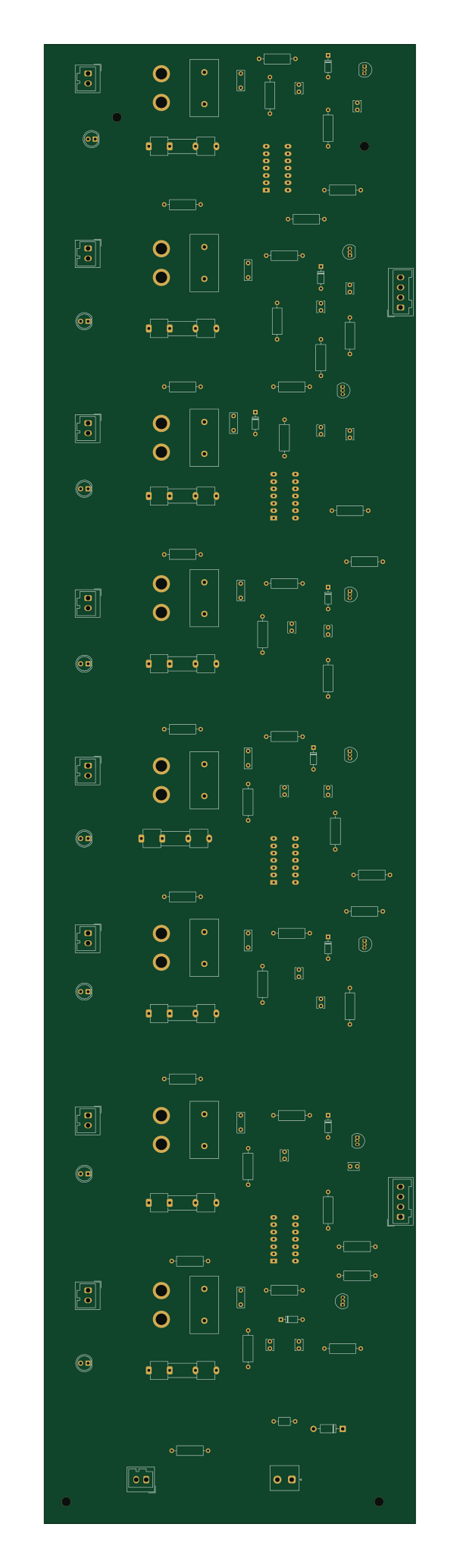
Block-Detector
129.5 × 515.6 mm130 parts2LNo license0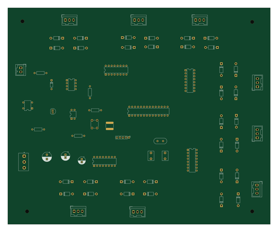 AVR/Arduino
Motor-Board
225.5 × 186 mm66 parts2LNo license0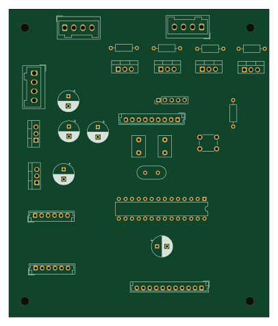 AVR/Arduino
Lights-Shild
100.3 × 118.6 mm37 parts2LNo license0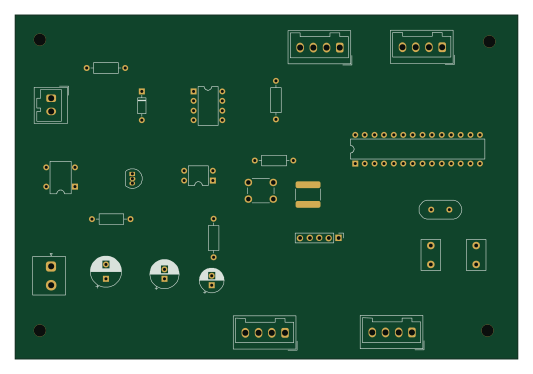 AVR/Arduino
Signal-Bord
133 × 91 mm26 parts2LNo license0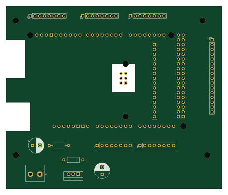 AVR/Arduino
IOExpander-Mega-Schild
114.3 × 96.5 mm14 parts2LNo license0
Similar boards
 AVR/Arduino
Magspoof
samyk
35 × 29 mm11 parts2LNo license4.2k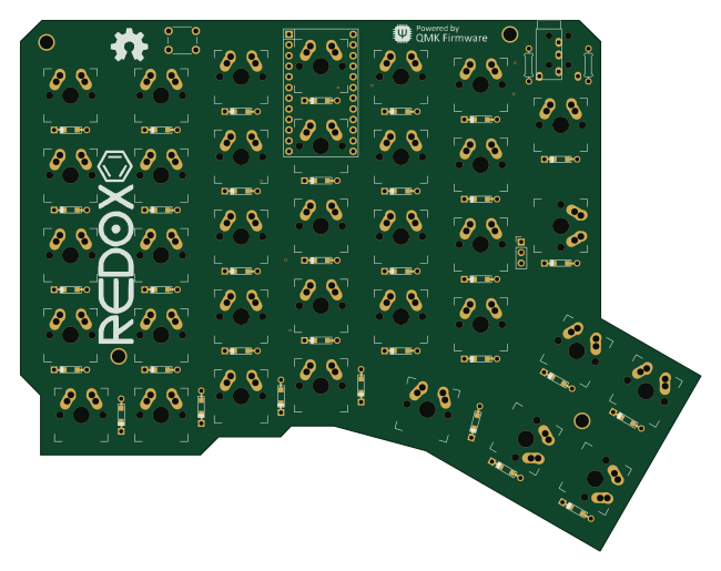 AVR/Arduino
Redox keyboard
mattdibi
162.2 × 126.5 mm77 parts2LMIT2.0k AVR/Arduino
Labrador
espotek-org
36.8 × 34.7 mm75 parts2LNo license1.2k AVR/Arduino
V4
stuartpittaway
30 × 50 mm38 parts2LCC-BY-NC-4.01.1k AVR/Arduino
ModuleV450
30 × 61.4 mm39 parts2LCC-BY-NC-4.01.1k AVR/Arduino
Discipline
coseyfannitutti
304.9 × 122.8 mm170 parts2LCC-BY-NC-4.01.0k