
Openlst hw

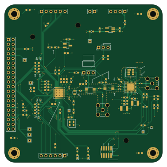
About the Openlst hw PCB
Openlst hw is an open source PCB design by MatthiasGeorgImhof, published on GitHub. It is a 4-layer board measuring 85 × 85 mm, with 104 components from 37 distinct parts.
Other key parts include the ADP150AUJZ-3.3-R7, CC1110, 0433BM15A0001, MIC803 and PE4250MLI. By type, the board carries 39 resistors, 32 capacitors, 10 connectors, 10 diodes, 8 ICs and 4 inductors.
It belongs with the rf & radio, science & space and test & measurement designs in this gallery.
From the project
CC1110 based Radio board. 435MHz. Modification of the OpenLST Reference Design to support $1K Cubesat
$1K CubeSat Design ==========================
This forked repo adapts the hardware from the OpenLST Reference into something that works for my $1K CubeSat project
Please note that this repository is desgined to be used as a submodule, since it depends on symbols & footprints in my 1KCubeSat_Hardware repository
This is an iteration on the OpenLST CC1110 based design, which itself is a simplified version of the TI CC1110 432 MHz reference design. While the CC1110 can operate over 400-470MHz, this board is designed to operate around 435MHz, within the 435MHz-438MHz US Amateur radio band. See…
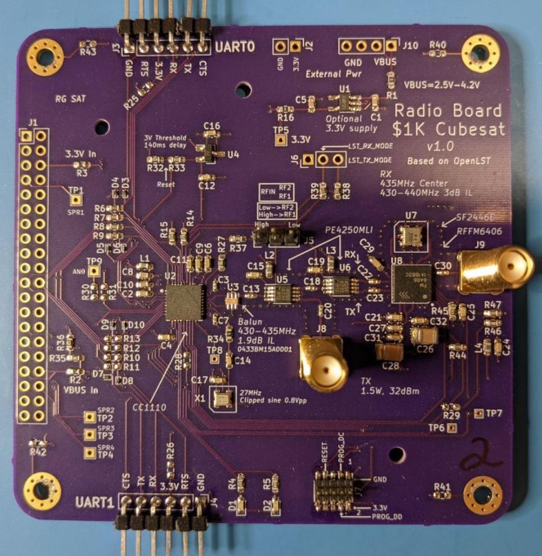
Main components on the Openlst hw
Openlst hw bill of materials (BOM)
104 components, 37 distinct parts — part numbers from the project's BOM.
| Qty | Part | Footprint | Refs |
|---|---|---|---|
| 1 | ADP150AUJZ-3.3-R7 | TSOT-23-5_HandSoldering | U1 |
| 1 | CC1110 | TI_CC_QFN36 | U2 |
| 1 | 0433BM15A0001 | Balun_Johanson_0896BM15A0001 | U3 |
| 1 | MIC803 | SOT-23_Handsoldering | U4 |
| 2 | PE4250MLI | MSOP-8_3x3mm_P0.65mm | U5, U6 |
| 1 | SF2446E | SF2446E | U7 |
| 1 | RFFM6406 | Qorvo_LGA_28_ThermalVias | U8 |
| 1 | TG2520SMN 27MHz | TG2520SMN | X1 |
| 1 | Conn_02x20_Odd_Even | PinHeader_2x20_P2.54mm_Vertical | J1 |
| 1 | EXT 3.3V | PinHeader_1x02_P2.54mm_Vertical | J2 |
| 1 | UART0 | PinHeader_1x06_P2.54mm_Vertical | J3 |
| 1 | UART1 | PinHeader_1x06_P2.54mm_Vertical | J4 |
| 1 | Switch Select | PinHeader_1x03_P2.54mm_Vertical | J5 |
| 1 | Control Outputs | PinHeader_1x03_P2.54mm_Vertical | J6 |
| 1 | CC Prog/Debug | PinHeader_2x05_P1.27mm_Vertical_SMD | J7 |
| 1 | Conn_Coaxial | SMA_Amphenol_901-144_Vertical | J8 |
| 1 | ANT | SMA_Amphenol_901-144_Vertical | J9 |
| 1 | EXT VBUS | PinHeader_1x04_P2.54mm_Vertical | J10 |
| 2 | LED_SMD_RED | LED_0603_1608Metric_Pad1.05x0.95mm_HandSolder | D1, D2 |
| 8 | ESD9B5.0ST5G | D_SOD-923 | D3, D4, D5, D6, D7, D8, D9, D10 |
Show 17 more
| Qty | Part | Footprint | Refs |
|---|---|---|---|
| 4 | Z=1k @ 100M | L_0603_1608Metric_Pad1.05x0.95mm_HandSolder | L1, L2, L3, L4 |
| 3 | 4.7uF | C_0603_1608Metric_Pad1.08x0.95mm_HandSolder | C1, C5, C31 |
| 13 | 0.1uF | C_0603_1608Metric_Pad1.08x0.95mm_HandSolder | C2, C4, C6, C9, C15, C16, C17, C19 +5 |
| 8 | 220pF | C_0402_1005Metric_Pad0.74x0.62mm_HandSolder | C3, C7, C13, C18, C20, C22, C23, C30 |
| 4 | 1uF | C_0603_1608Metric_Pad1.08x0.95mm_HandSolder | C8, C10, C11, C27 |
| 2 | 0.01uF | C_0603_1608Metric_Pad1.08x0.95mm_HandSolder | C12, C14 |
| 2 | 47uF | C_1210_3225Metric_Pad1.33x2.70mm_HandSolder | C26, C28 |
| 15 | DNP | R_0603_1608Metric_Pad0.98x0.95mm_HandSolder | R1, R10, R11, R12, R13, R25, R26, R28 +7 |
| 2 | 10m | R_0603_1608Metric_Pad0.98x0.95mm_HandSolder | R2, R3 |
| 8 | 1K | R_0603_1608Metric_Pad0.98x0.95mm_HandSolder | R4, R5, R14, R15, R33, R37, R44, R45 |
| 6 | 100 | R_0603_1608Metric_Pad0.98x0.95mm_HandSolder | R6, R7, R8, R9, R38, R39 |
| 2 | 0 | R_0603_1608Metric_Pad0.98x0.95mm_HandSolder | R16, R34 |
| 1 | 56K | R_0603_1608Metric_Pad0.98x0.95mm_HandSolder | R27 |
| 2 | 47K | R_0603_1608Metric_Pad0.98x0.95mm_HandSolder | R32, R36 |
| 1 | 20K | R_0603_1608Metric_Pad0.98x0.95mm_HandSolder | R35 |
| 1 | 3.09K | R_0603_1608Metric_Pad0.98x0.95mm_HandSolder | R46 |
| 1 | 6.65K | R_0603_1608Metric_Pad0.98x0.95mm_HandSolder | R47 |
Openlst hw design files
The KiCad project lives in the MatthiasGeorgImhof/openlst-hw repository on GitHub; these links point at the commit this page was built from.
- Layoutopenlst-hw.kicad_pcb
- BOMbom/bom.csv
Openlst hw: common questions
How big is the Openlst hw PCB?
The Openlst hw measures 85 × 85 mm, has 4 copper layers and is 1.6 mm thick.
How many components are on the Openlst hw?
104 components, from 37 distinct parts, with part numbers taken from the project's own BOM. The full bill of materials is listed on this page.
Where can I download the Openlst hw design files?
From the MatthiasGeorgImhof/openlst-hw repository on GitHub, which has the KiCad layout and the BOM; the links under Design files point to each one.
Can I use the Openlst hw design in my own project?
The repository has no license, so all rights stay with MatthiasGeorgImhof. Use it as a reference, and ask the author before reusing the design.
Similar boards
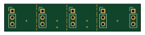
StackLink
gusmanb
52.3 × 10.5 mm5 parts2LGPL-3.05.0k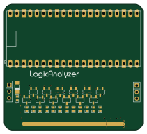
AnalyzerBoxPCB fork
52.7 × 47.9 mm54 parts4LGPL-3.05.0k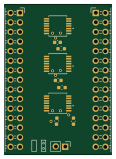
LevelShifter
28.3 × 39.8 mm21 parts2LGPL-3.05.0k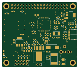
Radioberry juice
pa3gsb
65 × 56 mm87 parts2LNo license675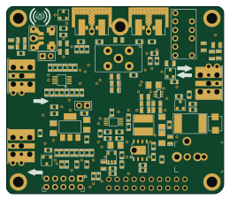
Radioberry preamp
65 × 56 mm137 parts2LNo license675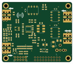
Hat
65 × 56 mm81 parts2LNo license675