
Gobox power

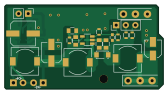
About the Gobox power PCB
Gobox power is an open source PCB design by mfhepp, published on GitHub. It is a 2-layer board measuring 41.9 × 22.2 mm, with 38 components from 31 distinct parts.
Other key parts include the SC4503. By type, the board carries 10 resistors, 8 capacitors, 3 connectors, 3 diodes, 3 inductors and 2 transistors.
It belongs with the power & battery and rf & radio designs in this gallery.
From the project
A 6-9-12V DC-DC boost converter for QRP rigs from 4 NiMH cells (or 2S LiPo with minor mods), e.g. Mountain Topper MTR-3B and MTR-5B.
Note: This is work-in-progress. I will remove this message when the materials are ready for use.
The board was designed for the Mountain Topper SOTA GoBox project, but can be used for any other similar project.
The boost converter is carefully designed to minimize RF emissions and noise on the output and output so that it does not impact the reception of weak radio signals in amateur radio transceivers.
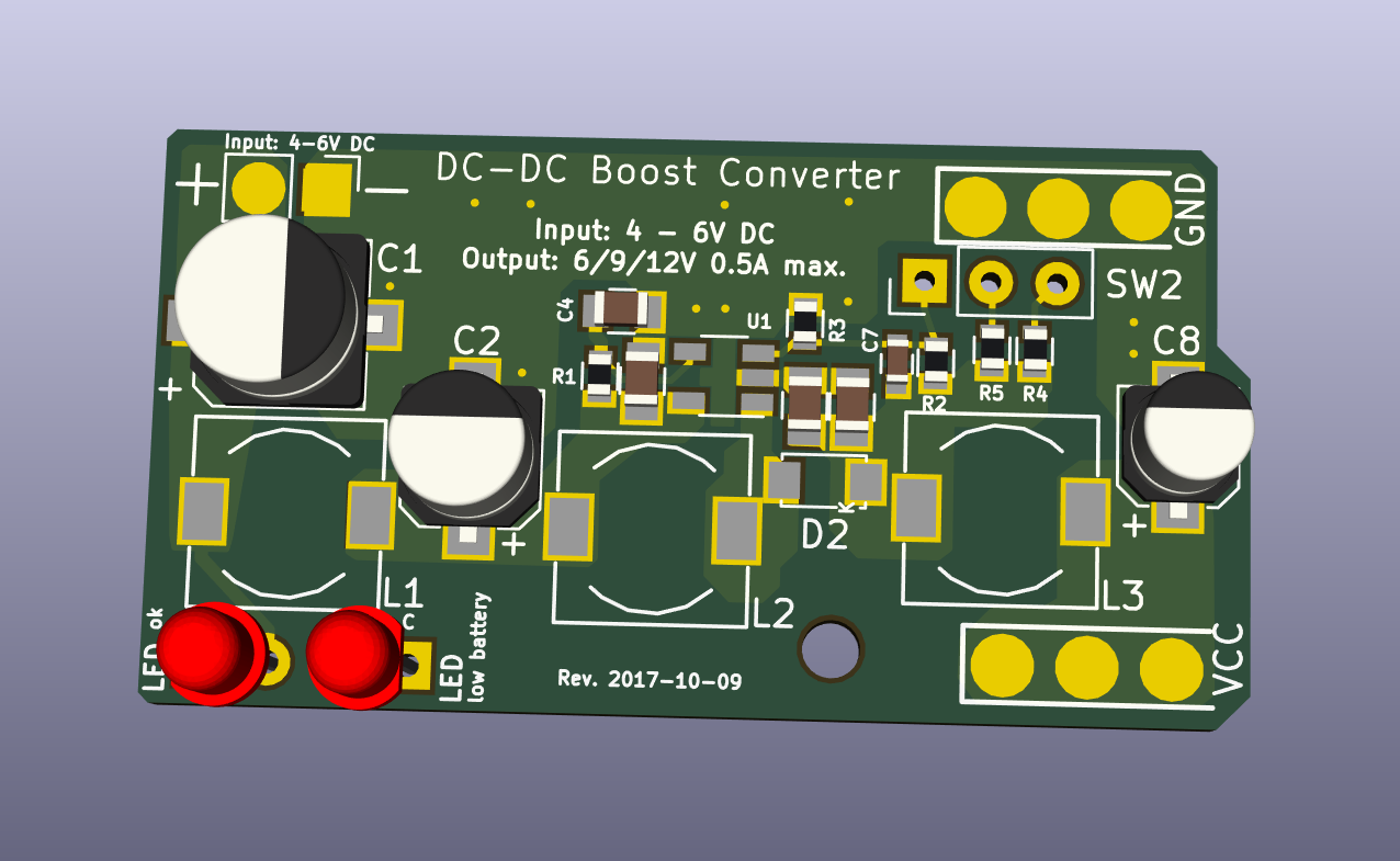
Main components on the Gobox power
Gobox power bill of materials (BOM)
38 components, 31 distinct parts.
| Qty | Part | Footprint | Refs |
|---|---|---|---|
| 1 | SC4503 | TSOT-23-5 | U1 |
| 2 | BC847 | SOT-23 | Q1, Q2 |
| 1 | DC_JACK | Generic_2-Pin_Connector_0.8mm | J1 |
| 1 | RIG_VCC | SolderWirePad_3x_0-8mmDrill | J2 |
| 1 | RIG_GND | SolderWirePad_3x_0-8mmDrill | J3 |
| 1 | 4.8V 4-cell NiMH Battery | not_on_board | BT1 |
| 1 | 2.5MM | not_on_board | CHARGE1 |
| 1 | 2.1MM | not_on_board | EXT_BATTERY1 |
| 1 | Polyfuse 1.85/3A | not_on_board | F1 |
| 1 | ON | not_on_board | SW1 |
| 1 | PWR_LEVEL | SW2-3pins | SW2 |
| 1 | red | LED_D3.0mm-external | LOW1 |
| 1 | green | LED_D3.0mm-external | PWR1 |
| 1 | 1N5822 | not_on_board | D1 |
| 1 | SS14L | D_SubSMA | D2 |
| 1 | BZX84-3.9V | SOT-23 | D3 |
| 3 | 4.7u/2A | Choke_SMD_7.3x7.3_H4.5 | L1, L2, L3 |
| 1 | 33u/16V low ESR | CP_Elec_6.3x5.3 | C1 |
| 1 | 47u/16V | CP_Elec_5x5.8 | C2 |
| 4 | 10u/25V | C_0805 | C3, C4, C5, C6 |
Show 11 more
| Qty | Part | Footprint | Refs |
|---|---|---|---|
| 1 | 15p | C_0603 | C7 |
| 1 | 10u/25V | CP_Elec_4x5.8 | C8 |
| 1 | 100k | R_0603 | R1 |
| 1 | 430k | R_0603 | R2 |
| 1 | 51k | R_0603 | R3 |
| 1 | 360k | R_0603 | R4 |
| 1 | 1.2M | R_0603 | R5 |
| 1 | 1k | R_0603 | R6 |
| 1 | 10k | R_0603 | R7 |
| 2 | 220 | R_0603 | R8, R10 |
| 1 | 47k | R_0603 | R9 |
Gobox power design files
The KiCad project lives in the mfhepp/gobox-power repository on GitHub; these links point at the commit this page was built from.
Gobox power: common questions
How big is the Gobox power PCB?
The Gobox power measures 41.9 × 22.2 mm, has 2 copper layers and is 1.6 mm thick.
How many components are on the Gobox power?
38 components, from 31 distinct parts. The full bill of materials is listed on this page.
Where can I download the Gobox power design files?
From the mfhepp/gobox-power repository on GitHub, which has the KiCad layout; the links under Design files point to each one.
Can I use the Gobox power design in my own project?
The repository has no license, so all rights stay with mfhepp. Use it as a reference, and ask the author before reusing the design.
Similar boards

Stack chan
stack-chan
50 × 50 mm33 parts2LApache-2.01.7k
Display Carrier
AxxAxx
35.6 × 58.2 mm5 parts2LGPL-3.01.7k
ControllerCurrentShuntAddOn
stuartpittaway
26 × 16.9 mm9 parts2LCC-BY-NC-4.01.1k
Module 16S PassiveBalanceAddOn
61 × 74 mm86 parts2LCC-BY-NC-4.01.1k
TemperaturePCB PANEL
116 × 75.5 mm178 parts2LCC-BY-NC-4.01.1k
ProgrammingAdapter
10.5 × 83 mm3 parts2LCC-BY-NC-4.01.1k