
JBclone soldering station

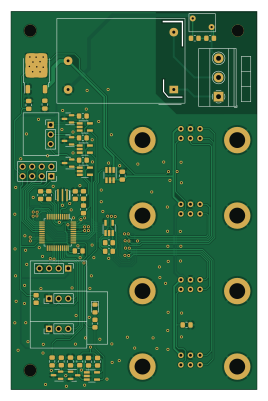
About the JBclone soldering station PCB
JBclone soldering station is an open source STM32 PCB design by Minu-IU3IRR, published on GitHub. It is a 2-layer board measuring 65 × 100 mm, with 52 components from 26 distinct parts.
Its main chip is the STM32F103C8T6, from the STM32 family. Other key parts include the LMV321, TPS22919DCKR, 24FC04HT and LD1117DT33. By type, the board carries 17 resistors, 10 connectors, 8 ICs, 8 capacitors, 5 diodes and 1 transistor.
From the project
Multi channel DIY soldering station with JBC tip support
A high-performance open hardware soldering station designed to support JBC and other thermocouple-based soldering tips. This project aims to deliver professional-grade thermal control and user experience at a fraction of the cost of a commercial JBC system.
The system provides multi-channel support, each with independent temperature feedback loops based on PID control. It includes modular PCB designs, 3D-printable case that fits in a standard 200x200mm 3d printer, STM32F103 microcontroller, Nextion HMI interface
Main components on the JBclone soldering station
JBclone soldering station bill of materials (BOM)
52 components, 26 distinct parts — part numbers from the project's BOM.
| Qty | Part | Footprint | Refs |
|---|---|---|---|
| 1 | STM32F103C8T6 | LQFP-48_7x7mm_P0.5mm | U1 |
| 1 | LMV321 | SOT-23-5_HandSoldering | U2 |
| 1 | TPS22919DCKR | SOT-23-6_Handsoldering | U3 |
| 1 | 24FC04HT | SOT-23-5_HandSoldering | U4 |
| 3 | LMV321 | SOT-23-5_HandSoldering | U5, U6, U7 |
| 1 | LD1117DT33 | TO-252-2 | U10 |
| 1 | MMBT3904 | SOT-23 | Q1 |
| 1 | 8MHZ 8MHz | Resonator_SMD_Murata_CSTxExxV-3Pin_3.0x1.1mm_HandSoldering | Y2 |
| 1 | 664-G800W304018EU HMI | PinHeader_1x04_P2.54mm_Vertical | J1 |
| 4 | PB_2 | DaughterBoard | J2, J4, J5, J10 |
| 1 | 664-G800W305018EU USB | PinHeader_1x03_P2.54mm_Vertical | J3 |
| 1 | 732-61300621821 GPIO | PinSocket_2x04_P2.54mm_Vertical | J6 |
| 1 | 664-G800W305018EU STlink | PinHeader_1x03_P2.54mm_Vertical | J7 |
| 1 | 277-1264 PWR | TerminalBlock_Phoenix_MKDS-1,5-3-5.08_1x03_P5.08mm_Horizontal | J8 |
| 1 | 664-G800W305018EU STAND | PinHeader_1x03_P2.54mm_Vertical | J9 |
| 1 | IRM-02-5 | Converter_ACDC_MeanWell_IRM-02-xx_THT | PS1 |
| 1 | 270KD07 | RV_Disc_D7mm_W4.8mm_P5mm | RV1 |
| 1 | LED | LED_0805_2012Metric_Pad1.15x1.40mm_HandSolder | D1 |
| 4 | BAT54S | SOT-23 | D2, D3, D4, D5 |
| 4 | 100N 100n | C_0805_2012Metric_Pad1.18x1.45mm_HandSolder | C1, C6, C12, C13 |
Show 6 more
| Qty | Part | Footprint | Refs |
|---|---|---|---|
| 4 | 10UF 10uF | C_0805_2012Metric_Pad1.18x1.45mm_HandSolder | C2, C3, C7, C17 |
| 4 | 10K 10k | R_0805_2012Metric_Pad1.20x1.40mm_HandSolder | R1, R11, R14, R15 |
| 5 | 1.5K 1.5k | R_0805_2012Metric_Pad1.20x1.40mm_HandSolder | R2, R3, R9, R10, R13 |
| 5 | 10k | R_0805_2012Metric_Pad1.20x1.40mm_HandSolder | R4, R5, R6, R7, R8 |
| 1 | 100K 100k | R_0805_2012Metric_Pad1.20x1.40mm_HandSolder | R12 |
| 2 | 590K 590k | R_0805_2012Metric_Pad1.20x1.40mm_HandSolder | R23, R25 |
JBclone soldering station design files
The KiCad project lives in the Minu-IU3IRR/JBclone-soldering-station repository on GitHub; these links point at the commit this page was built from.
JBclone soldering station: common questions
What microcontroller does the JBclone soldering station use?
The JBclone soldering station is built around the STM32F103C8T6, from the STM32 family.
How big is the JBclone soldering station PCB?
The JBclone soldering station measures 65 × 100 mm, has 2 copper layers and is 1.6 mm thick.
How many components are on the JBclone soldering station?
52 components, from 26 distinct parts, with part numbers taken from the project's own BOM. The full bill of materials is listed on this page.
Where can I download the JBclone soldering station design files?
From the Minu-IU3IRR/JBclone-soldering-station repository on GitHub, which has the KiCad layout, the schematic and the BOM; the links under Design files point to each one.
Can I use the JBclone soldering station design in my own project?
The repository has no license, so all rights stay with Minu-IU3IRR. Use it as a reference, and ask the author before reusing the design.
Can I test firmware for the JBclone soldering station without the hardware?
Yes. HardLabs builds a simulation of the board from its netlist and BOM, so you can run and debug STM32 firmware against it before you order a PCB.
Similar boards
 STM32
STM32LumenPnP Motherboard
opulo-inc
149 × 95 mm296 parts4LCC-BY-SA-4.03.7k STM32
STM32AxxSolder
AxxAxx
39 × 82.5 mm122 parts2LGPL-3.01.7k STM32
STM32AIOC
skuep
21 × 31.5 mm47 parts2LMIT1.4k STM32
STM32Ferris
pierrechevalier83
208.8 × 86.8 mm102 parts2LSHL-2.11.3k STM32
STM32Module 16S
stuartpittaway
71.1 × 89.6 mm113 parts4LCC-BY-NC-4.01.1k STM32
STM32Djinn
tzarc
192.3 × 150.5 mm216 parts2LCERN-OHL-S-2.0988