
MioLink adapter

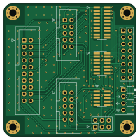
About the MioLink adapter PCB
MioLink adapter is an open source PCB design by Misaka0x2730, published on GitHub under the GPL-3.0 license. It is a 2-layer board measuring 50 × 50 mm, with 9 components from 9 distinct parts.
It belongs with the usb & debug tools designs in this gallery.
From the project
ARM JTAG/SWD debugger (BlackMagic port) based on RP2040.
MioLink adapter bill of materials (BOM)
9 components, 9 distinct parts — part numbers from the project's BOM.
| Qty | Part | Footprint | Refs |
|---|---|---|---|
| 1 | 10-pin Cortex Debug 0.1" | IDC-Header_2x05_P2.54mm_Vertical | J1 |
| 1 | 10-pin Cortex Debug 0.05" | PinHeader_2x05_P1.27mm_Vertical_SMD | J2 |
| 1 | ST-Link clone | IDC-Header_2x05_P2.54mm_Vertical | J3 |
| 1 | TC2030-IDC-NL | PinHeader_2x03_P2.54mm_Vertical | J4 |
| 1 | Standard JTAG | IDC-Header_2x10_P2.54mm_Vertical | J5 |
| 1 | 20-pin Cortex Debug + ETM | PinHeader_2x10_P1.27mm_Vertical_SMD | J6 |
| 1 | ST-Link v3 STDC14 | PinHeader_2x07_P1.27mm_Vertical_SMD | J7 |
| 1 | Serial Interconnection | PinHeader_2x08_P2.54mm_Vertical | J8 |
| 1 | Target Serial | PinHeader_1x04_P2.54mm_Horizontal | J9 |
MioLink adapter design files
The KiCad project lives in the Misaka0x2730/MioLink repository on GitHub; these links point at the commit this page was built from.
MioLink adapter: common questions
How big is the MioLink adapter PCB?
The MioLink adapter measures 50 × 50 mm, has 2 copper layers and is 1.6 mm thick.
How many components are on the MioLink adapter?
9 components, from 9 distinct parts, with part numbers taken from the project's own BOM. The full bill of materials is listed on this page.
Where can I download the MioLink adapter design files?
From the Misaka0x2730/MioLink repository on GitHub, which has the KiCad layout, the schematic and the BOM; the links under Design files point to each one.
Can I use the MioLink adapter design in my own project?
Yes, under the terms of its GPL-3.0 license, which Misaka0x2730 chose for the repository.
More boards in MioLink
Similar boards
USB Hub Test
osy
50 × 50 mm85 parts4LCC-BY-4.0703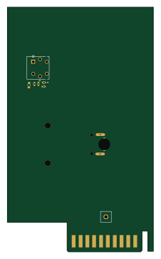
XG Station Power
54.3 × 91 mm9 parts2LCC-BY-4.0703
FW-EC-DongleHiderPlus
LeoDJ
28.2 × 26.1 mm14 parts4LCERN-OHL-W-2.0490
Adapter tsop48
bbogush
48 × 33 mm3 parts2LGPL-3.0389
Adapter tsop48 solder
48 × 33 mm3 parts2LGPL-3.0389
Adapter soic8 solder
48 × 20 mm3 parts2LGPL-3.0389