
MioLink

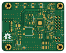
About the MioLink PCB
MioLink is an open source RP2040/RP2350 PCB design by Misaka0x2730, published on GitHub under the GPL-3.0 license. It is a 4-layer board measuring 53 × 42 mm, with 92 components from 36 distinct parts.
Its main chip is the RP2040, from the RP2040/RP2350 family. Other key parts include the TLV62568DBV, USBLC6-2SC6, W25Q16JVSSIQ, TPS2553DBV and LMV321IDCKR. By type, the board carries 33 capacitors, 33 resistors, 10 ICs, 4 connectors, 4 diodes and 4 inductors.
It belongs with the usb & debug tools designs in this gallery.
From the project
ARM JTAG/SWD debugger (BlackMagic port) based on RP2040.
Main components on the MioLink
MioLink bill of materials (BOM)
92 components, 36 distinct parts — part numbers from the project's BOM.
| Qty | Part | Footprint | Refs |
|---|---|---|---|
| 1 | TLV62568DBV | SOT-23-5 | U1 |
| 1 | USBLC6-2SC6 | SOT-23-6 | U2 |
| 1 | W25Q16JVSSIQ W25Q16JVSS | SOIC-8_5.23x5.23mm_P1.27mm | U3 |
| 1 | TPS2553DBV TPS2553DBVR | SOT-23-6 | U4 |
| 1 | LMV321IDCKR | SOT-353_SC-70-5 | U5 |
| 1 | RP2040 | QFN-56-1EP_7x7mm_P0.4mm_EP3.2x3.2mm | U6 |
| 4 | SN74LVC2T45DCU 74LVC2T45DC | VSSOP-8_2.3x2mm_P0.5mm | U7, U8, U9, U10 |
| 1 | BSS138LT1G BSS138 | SOT-23 | Q1 |
| 1 | ABM8-272-T3 12MHz | Crystal_SMD_3225-4Pin_3.2x2.5mm | Y1 |
| 1 | TYPE-C-31-M-12A USB | USB_C_Receptacle_HRO_TYPE-C-31-M-12 | J1 |
| 1 | 20021121-00010T4LF Probe MCU SWD | PinHeader_2x05_P1.27mm_Vertical_SMD | J2 |
| 1 | PZ254-2-02-W-8.5 Target UART connector | PinHeader_2x02_P2.54mm_Horizontal | J3 |
| 1 | 0502A001A1BC Target connector | IDC-Header_2x05_P2.54mm_Horizontal | J4 |
| 1 | B3S-1000 BOOT | SW_SPST_B3S-1000 | SW1 |
| 1 | GND | TestPoint_Keystone_5000-5004_Miniature | TP3 |
| 1 | XL-3216SYGC PWR | LED_1206_3216Metric | D1 |
| 1 | XL-3216SURC ERR | LED_1206_3216Metric | D2 |
| 1 | XL-3216UOC ACT | LED_1206_3216Metric | D3 |
| 1 | XL-3216UYC SER | LED_1206_3216Metric | D4 |
| 1 | BLM18PG330SN1D 33Ohm/100MHz | L_0603_1608Metric | FB1 |
Show 16 more
| Qty | Part | Footprint | Refs |
|---|---|---|---|
| 2 | BLM18PG121SN1D 120Ohm/100MHz | L_0603_1608Metric | FB2, FB3 |
| 1 | LPS3015-222MRC 2.2uH | L_Taiyo-Yuden_NR-30xx | L1 |
| 3 | CL10A106KP8NNNC 10u | C_0603_1608Metric | C1, C2, C4 |
| 1 | CC0402CRNPO9BN6R8 6.8pF | C_0402_1005Metric | C3 |
| 7 | CL05A105KA5NQNC 1u | C_0402_1005Metric | C5, C6, C7, C9, C12, C16, C25 |
| 20 | CL05B104KO5NNNC 100n | C_0402_1005Metric | C8, C10, C14, C15, C17, C18, C19, C20 +12 |
| 2 | CC0402JRNPO9BN160 16p | C_0402_1005Metric | C11, C13 |
| 8 | 0402WGF1001TCE 1k | R_0402_1005Metric | R1, R6, R7, R8, R14, R18, R28, R32 |
| 2 | 0402WGF5101TCE 5.1k | R_0402_1005Metric | R2, R5 |
| 1 | AC0402FR-07453KL 453k | R_0402_1005Metric | R3 |
| 7 | 0402WGF1003TCE 100k | R_0402_1005Metric | R4, R9, R10, R11, R12, R27, R29 |
| 3 | 0402WGF1002TCE 10k | R_0402_1005Metric | R13, R19, R30 |
| 1 | 0402WGF7502TCE 75k 1% | R_0402_1005Metric | R15 |
| 2 | 0402WGF270JTCE 27 | R_0402_1005Metric | R16, R17 |
| 7 | 0402WGF1000TCE 100 | R_0402_1005Metric | R20, R21, R22, R23, R24, R25, R26 |
| 2 | 0402WGF4701TCE 4.7k | R_0402_1005Metric | R31, R33 |
MioLink design files
The KiCad project lives in the Misaka0x2730/MioLink repository on GitHub; these links point at the commit this page was built from.
MioLink: common questions
What microcontroller does the MioLink use?
The MioLink is built around the RP2040, from the RP2040/RP2350 family.
How big is the MioLink PCB?
The MioLink measures 53 × 42 mm, has 4 copper layers and is 1.6554 mm thick.
How many components are on the MioLink?
92 components, from 36 distinct parts, with part numbers taken from the project's own BOM. The full bill of materials is listed on this page.
Where can I download the MioLink design files?
From the Misaka0x2730/MioLink repository on GitHub, which has the KiCad layout, the schematic and the BOM; the links under Design files point to each one.
Can I use the MioLink design in my own project?
Yes, under the terms of its GPL-3.0 license, which Misaka0x2730 chose for the repository.
Can I test firmware for the MioLink without the hardware?
Yes. HardLabs builds a simulation of the board from its netlist and BOM, so you can run and debug RP2040/RP2350 firmware against it before you order a PCB.
More boards in MioLink
Similar boards
 RP2040/RP2350
Open Book Abridged Edition
joeycastillo
85 × 115 mm29 parts2LCC-BY-SA-4.08.1k RP2040/RP2350
Corne
foostan
277.2 × 107.5 mm164 parts2LCC-BY-4.07.7k RP2040/RP2350
Corne
277.2 × 107.5 mm164 parts2LCC-BY-4.07.7k RP2040/RP2350
Jitx design
gusmanb
55.5 × 65 mm26 parts4LGPL-3.05.0k RP2040/RP2350
LogicAnalyzer
57 × 55.2 mm6 parts2LGPL-3.05.0k RP2040/RP2350
Main
google
98 × 71 mm102 parts2LApache-2.02.9k