
RFSWITCH01

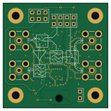
About the RFSWITCH01 PCB
RFSWITCH01 is an open source PCB design by mlab-modules, published on GitHub under the GPL-3.0 license. It is a 2-layer board measuring 40.1 × 40.1 mm, with 41 components from 22 distinct parts.
Other key parts include the TPS22945DCKR, PE4259 and SPF5189Z. By type, the board carries 10 connectors, 10 capacitors, 6 inductors, 6 resistors, 4 ICs and 4 diodes.
It belongs with the rf & radio and robotics & motion designs in this gallery.
From the project
The module featuring two RF switches. Designed for radio transceivers with separate input and output.
The RFSWITCH01 is an MLAB module that incorporates a pair of RF switches, specifically the PE4259. from Peregrine Semiconductor. This module is designed to connect to a radio transceiver that has separate radio input and output. Thanks to the use of two switches, the module allows connecting two antennas. The individual switches are controlled by a simple digital input signal. With RFSWITCH01, a transceiver can work with the support of MIMO 2x2. The module is typically assembled for frequencies of 433MHz and 868MHz.
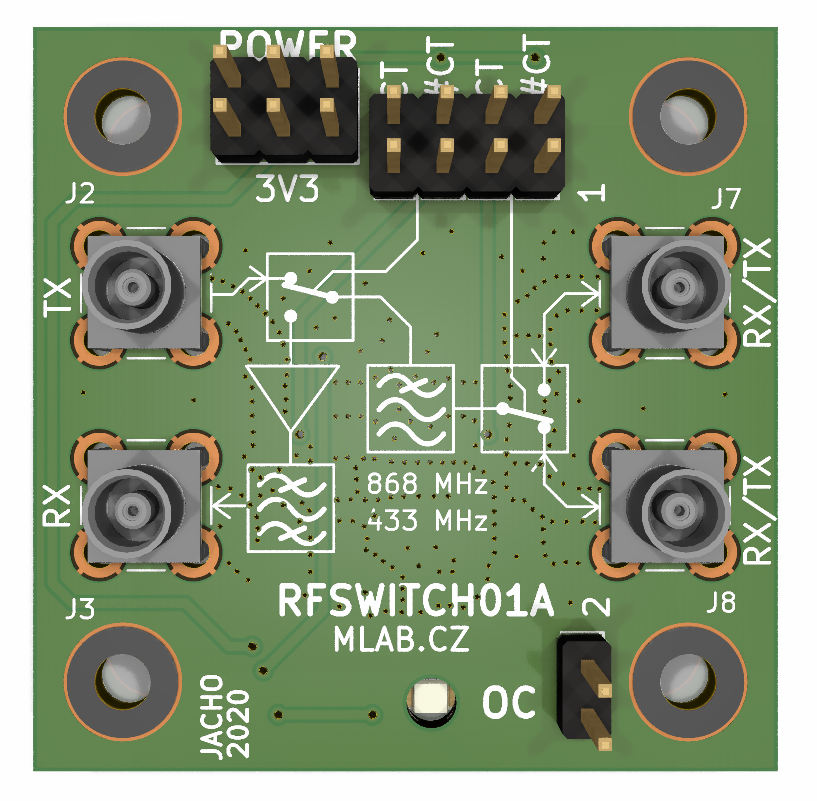
Main components on the RFSWITCH01
RFSWITCH01 bill of materials (BOM)
41 components, 22 distinct parts — part numbers from the project's BOM.
| Qty | Part | Footprint | Refs |
|---|---|---|---|
| 1 | TPS22945DCKR | SOT-353_SC-70-5 | U1 |
| 2 | PE4259 | SOT-363_SC-70-6 | U2, U4 |
| 1 | SPF5189Z | SOT-89-3 | U3 |
| 1 | HEADER_2X03_PARALLEL HEADER_2x03_PARALLEL | Straight_2x03 | J1 |
| 4 | SMA | SMB_Jack_Vertical | J2, J3, J7, J8 |
| 5 | HEADER_2x01_PARALLEL | Straight_2x01 | J4, J5, J6, J9, J10 |
| 1 | SAW_AFS434S3-T_AFS869S3-T | ABRACON_AFS | FL1 |
| 1 | M4 | D_SMA | D1 |
| 2 | BZV55C-3,6V | D_MiniMELF | D2, D3 |
| 1 | RED | LED_1206 | D4 |
| 1 | 74279204 | L_0805_2012Metric | L1 |
| 1 | 100nH | L_0805_2012Metric | L2 |
| 1 | 1N5H 1n5H | L_0805_2012Metric | L3 |
| 2 | 100nH | SMD-0805 | L4, L5 |
| 1 | 6N8 6n8 | SMD-0805 | L6 |
| 1 | 10UF 10uF | SMD-0805 | C1 |
| 2 | 100pF | SMD-0805 | C2, C4 |
| 1 | 100NF 100nF | SMD-0805 | C3 |
| 4 | 1nF | SMD-0805 | C5, C6, C7, C8 |
| 2 | 2p2 | SMD-0805 | C9, C10 |
Show 2 more
| Qty | Part | Footprint | Refs |
|---|---|---|---|
| 5 | 10k | SMD-0805 | R1, R2, R3, R4, R5 |
| 1 | 330R | SMD-0805 | R6 |
RFSWITCH01 design files
The KiCad project lives in the mlab-modules/RFSWITCH01 repository on GitHub; these links point at the commit this page was built from.
RFSWITCH01: common questions
How big is the RFSWITCH01 PCB?
The RFSWITCH01 measures 40.1 × 40.1 mm, has 2 copper layers and is 1.6 mm thick.
How many components are on the RFSWITCH01?
41 components, from 22 distinct parts, with part numbers taken from the project's own BOM. The full bill of materials is listed on this page.
Where can I download the RFSWITCH01 design files?
From the mlab-modules/RFSWITCH01 repository on GitHub, which has the KiCad layout, the schematic and the BOM; the links under Design files point to each one.
Can I use the RFSWITCH01 design in my own project?
Yes, under the terms of its GPL-3.0 license, which mlab-modules chose for the repository.
Similar boards

Stack chan
stack-chan
50 × 50 mm33 parts2LApache-2.01.7k
Cube batteryboard
willem-pennings
95 × 95 mm4 parts2LGPL-3.01.1k
Mesabob
rene-dev
87.5 × 50 mm44 parts2LGPL-3.0979
Triple adapter
57 × 75 mm26 parts2LGPL-3.0979
Bob
100 × 100 mm140 parts2LGPL-3.0979
Trollerv2
100 × 75 mm33 parts4LGPL-3.0979