
電源基板

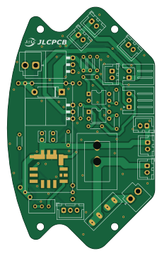
About the 電源基板 PCB
電源基板 is an open source PCB design by MUNAKATA-EPC, published on GitHub. It is a 2-layer board measuring 55.1 × 90 mm, with 34 components from 23 distinct parts.
Other key parts include the OKL-T_6-W12N-C and EL817. By type, the board carries 10 resistors, 8 connectors, 4 ICs, 4 capacitors, 2 transistors and 2 switches.
From the project
チームメンバー間の仲は良好です
Main components on the 電源基板
電源基板 bill of materials (BOM)
34 components, 23 distinct parts.
| Qty | Part | Footprint | Refs |
|---|---|---|---|
| 1 | OKL-T_6-W12N-C | DCDC-murata-6A | U1 |
| 1 | ~ | XL6009 | U2 |
| 2 | EL817 | DIP-4_W7.62mm | U3, U4 |
| 1 | PMOS | K15A20D | Q1 |
| 1 | NMOS | K15A20D | Q2 |
| 4 | Conn_01x02_Socket | JST_XH_B2B-XH-A_1x02_P2.50mm_Vertical | J1, J4, J8, J9 |
| 1 | Conn_01x02_Socket | JST_VH_B2P-VH_1x02_P3.96mm_Vertical | J3 |
| 1 | Conn_01x03_Socket | JST_XH_S3B-XH-A_1x03_P2.50mm_Horizontal | J5 |
| 1 | 電圧計 | JST_XH_B2B-XH-A_1x02_P2.50mm_Vertical | J6 |
| 1 | Conn_01x02_Socket | JST_XH_S2B-XH-A_1x02_P2.50mm_Horizontal | J7 |
| 1 | Battery | JST_VH_B2P-VH_1x02_P3.96mm_Vertical | BT1 |
| 1 | Fuse | fuse_socket | F1 |
| 1 | R_Potentiometer_Trim_US | Potentiometer_Bourns_3296W_Vertical | RV1 |
| 1 | SW_DIP_x01 | DS-850k | SW1 |
| 1 | SW_DIP_x01 | JST_XH_B3B-XH-A_1x03_P2.50mm_Vertical | SW2 |
| 1 | D | D_DO-15_P10.16mm_Horizontal | D2 |
| 2 | C | JST_XH_B2B-XH-A_1x02_P2.50mm_Vertical | C1, C4 |
| 2 | C | C_Disc_D3.8mm_W2.6mm_P2.50mm | C2, C3 |
| 2 | R | R_Axial_DIN0204_L3.6mm_D1.6mm_P5.08mm_Horizontal | R1, R2 |
| 2 | 2K | R_Axial_DIN0204_L3.6mm_D1.6mm_P5.08mm_Horizontal | R3, R7 |
Show 3 more
| Qty | Part | Footprint | Refs |
|---|---|---|---|
| 2 | 1K | R_Axial_DIN0204_L3.6mm_D1.6mm_P5.08mm_Horizontal | R4, R8 |
| 3 | 330 | R_Axial_DIN0204_L3.6mm_D1.6mm_P5.08mm_Horizontal | R5, R6, R9 |
| 1 | 10K | R_Axial_DIN0204_L3.6mm_D1.6mm_P5.08mm_Horizontal | R10 |
電源基板 design files
The KiCad project lives in the MUNAKATA-EPC/Amateras repository on GitHub; these links point at the commit this page was built from.
電源基板: common questions
How big is the 電源基板 PCB?
The 電源基板 measures 55.1 × 90 mm, has 2 copper layers and is 1.6 mm thick.
How many components are on the 電源基板?
34 components, from 23 distinct parts. The full bill of materials is listed on this page.
Where can I download the 電源基板 design files?
From the MUNAKATA-EPC/Amateras repository on GitHub, which has the KiCad layout and the schematic; the links under Design files point to each one.
Can I use the 電源基板 design in my own project?
The repository has no license, so all rights stay with MUNAKATA-EPC. Use it as a reference, and ask the author before reusing the design.
More boards in Amateras
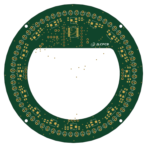
LINE Main
119.4 × 119.4 mm137 parts2LNo license1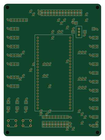 STM32
Stm32f446re breakout substrate
83.8 × 114.2 mm84 parts2LNo license1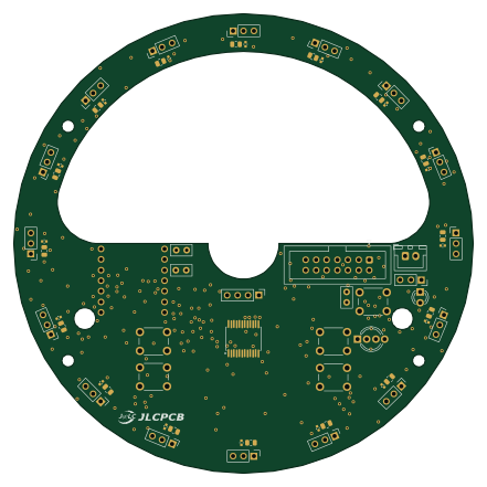
IR board syuuseibann
110 × 110 mm64 parts2LNo license1 RP2040/RP2350
Drive
53 × 72.8 mm39 parts4LNo license1 RP2040/RP2350
Main board
110 × 110 mm35 parts2LNo license1
Highway
118.8 × 42.4 mm10 parts2LNo license1