
Ftboost interleaved boost

About the Ftboost interleaved boost PCB
Ftboost interleaved boost is an open source PCB design by Naagdant, published on GitHub under the MIT license. It is a board, with 54 components from 33 distinct parts.
Other key parts include the AMC1300. By type, the board carries 2 ICs, 2 transistors, 2 relays, 2 diodes, 2 inductors and 1 connector.
It belongs with the power & battery designs in this gallery.
From the project
Fault-tolerant two-phase interleaved boost converter (48 V → 200 V) for EV buses: off-time template fault diagnosis and hybrid SSD/relay phase isolation. KiCad design, SPICE models and Python–ngspice co-simulation.
KiCad design, SPICE models and Python co-simulation code for the paper
A two-phase, 50 kHz, 48 V → 200 V interleaved boost converter that detects, classifies and isolates an open inductor, a stuck-on (shorted) switch or an open diode in either phase and keeps regulating on the remaining phase. Diagnosis uses only the per-phase current sensors: each off-time window of the sensed current is compared with a healthy template through the Pearson correlation and a load-independent slope ratio. Each phase is isolated on its input side by a solid-state disconnect (SSD) in series with a relay.
Main components on the Ftboost interleaved boost
Ftboost interleaved boost bill of materials (BOM)
54 components, 33 distinct parts.
| Qty | Part | Footprint | Refs |
|---|---|---|---|
| 2 | AMC1300 | U1, U2 | |
| 2 | 650V 80mR | Q1, Q2 | |
| 1 | MCU/DSP interface (ADC in, PWM out) | J1 | |
| 1 | 100u | CIN1 | |
| 1 | 14u 450V film | COUT1 | |
| 2 | UF4007 | DFW1, DFW2 | |
| 2 | SMBJ100A | DZ1, DZ2 | |
| 2 | PWM_GDRV | EG1, EG2 | |
| 2 | G2RL-1A 12V | K1, K2 | |
| 2 | 60m (L DCR) | RDCR1, RDCR2 | |
| 1 | 10m ESR | RESR1 | |
| 1 | 1.99Meg | RFB1 | |
| 1 | 10k | RFB2 | |
| 1 | 200 (1 A @ 200 V) | RLOAD1 | |
| 2 | 10m Kelvin | RSH1, RSH2 | |
| 1 | 20m | RSRC1 | |
| 2 | FAULT: open D | SOD1, SOD2 | |
| 2 | FAULT: open L | SOL1, SOL2 | |
| 2 | SSD: solid-state disconnect | SSD1, SSD2 | |
| 2 | FAULT: short Q | SSW1, SSW2 |
Show 13 more
| Qty | Part | Footprint | Refs |
|---|---|---|---|
| 1 | 3.3V (AMC1300 VDD2) | VAUX1 | |
| 1 | carrier td=0 | VCAR1 | |
| 1 | carrier td=10u | VCAR2 | |
| 2 | CTRL duty (0.76) | VDUTY1, VDUTY2 | |
| 2 | INJ open-D (1=ok) | VFOD1, VFOD2 | |
| 2 | INJ open-L (1=ok) | VFOL1, VFOL2 | |
| 2 | INJ short-Q (0=ok) | VFSW1, VFSW2 | |
| 1 | 48V | VIN1 | |
| 2 | 5V iso DC/DC | VISO1, VISO2 | |
| 2 | CTRL relay coil (12V) | VRLY1, VRLY2 | |
| 2 | CTRL SSD gate (1=on) | VSSD1, VSSD2 | |
| 2 | 650V SiC SBD | D1, D2 | |
| 2 | 1mH | L1, L2 |
Ftboost interleaved boost design files
The KiCad project lives in the Naagdant/ftboost-interleaved-boost repository on GitHub; these links point at the commit this page was built from.
- Schematickicad/ft_boost/ft_boost.kicad_sch
Ftboost interleaved boost: common questions
How many components are on the Ftboost interleaved boost?
54 components, from 33 distinct parts. The full bill of materials is listed on this page.
Where can I download the Ftboost interleaved boost design files?
From the Naagdant/ftboost-interleaved-boost repository on GitHub, which has the schematic; the links under Design files point to each one.
Can I use the Ftboost interleaved boost design in my own project?
Yes, under the terms of its MIT license, which Naagdant chose for the repository.
Similar boards

EinkPDA screen
TalismanDesign
95 × 54 mm27 parts2LApache-2.02.0k
Stack chan
stack-chan
50 × 50 mm33 parts2LApache-2.01.7k
Display Carrier
AxxAxx
35.6 × 58.2 mm5 parts2LGPL-3.01.7k
ProgrammingAdapter
stuartpittaway
10.5 × 83 mm3 parts2LCC-BY-NC-4.01.1k
TemperaturePCB PANEL
116 × 75.5 mm178 parts2LCC-BY-NC-4.01.1k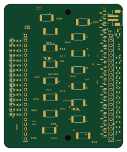
Module 16S PassiveBalanceAddOn
61 × 74 mm86 parts2LCC-BY-NC-4.01.1k