
LimiterBoard

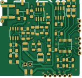
About the LimiterBoard PCB
LimiterBoard is an open source STM32 PCB design by nietamten, published on GitHub. It is a 2-layer board measuring 40.1 × 38.3 mm, with 45 components from 26 distinct parts.
Its main chip is the STM8S003F3P, from the STM32 family. Other key parts include the L78L05_SO8 and NE5534. By type, the board carries 18 resistors, 9 diodes, 9 capacitors, 4 ICs, 3 connectors and 1 jumper.
It belongs with the power & battery designs in this gallery.
From the project
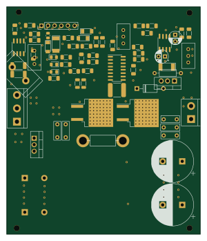
NCP1034 buck with regulated output voltage, output current, minimum input voltage
Kicad project of NCP1034 based buck converter with features useful for solar panels and batteries.
After adjusting compensation network with "Design Spreadsheet for NCP1034" seems to be stable If it's not, see troubleshooting section.
There is separate output anode with current limit. It can be used simultaneously with that not limited. For example battery can be charged with limiting (to not damage it by overcurrent) and some device can use non-limited anode to not distgurb charging. It is not working ideally (limited output can limit that not limited) but can be helpfull.
Main components on the LimiterBoard
LimiterBoard bill of materials (BOM)
45 components, 26 distinct parts.
| Qty | Part | Footprint | Refs |
|---|---|---|---|
| 1 | STM8S003F3P | TSSOP-20_4.4x6.5mm_P0.65mm | U1 |
| 1 | L78L05_SO8 | SOIC-8_3.9x4.9mm_P1.27mm | U2 |
| 2 | NE5534 | SOIC-8_3.9x4.9mm_P1.27mm | U3, U12 |
| 1 | ST-LINK | PinHeader_1x04_P2.54mm_Horizontal | J1 |
| 1 | UART | PinHeader_1x03_P2.54mm_Horizontal | J2 |
| 1 | board | PinHeader_1x06_P2.54mm_Horizontal | J3 |
| 1 | Jumper_2_Open | PinHeader_1x02_P2.54mm_Vertical | JP1 |
| 1 | 1k | Potentiometer_Bourns_3269W_Vertical | RV1 |
| 2 | 5-15v | D_MiniMELF | D1, D8 |
| 3 | LED | LED_1206_3216Metric_Pad1.42x1.75mm_HandSolder | D2, D6, D12 |
| 3 | D | D_1210_3225Metric | D3, D4, D7 |
| 1 | GREEN | LED_1206_3216Metric_Pad1.42x1.75mm_HandSolder | D5 |
| 7 | 100n | C_1206_3216Metric | C1, C3, C5, C6, C22, C32, C42 |
| 1 | 470-3300n | C_1206_3216Metric | C2 |
| 1 | 0.33uf | C_1206_3216Metric | C4 |
| 3 | R | R_1206_3216Metric | R1, R16, R22 |
| 2 | 47k | R_1206_3216Metric_Pad1.30x1.75mm_HandSolder | R2, R3 |
| 2 | 3.3k | R_1206_3216Metric | R4, R6 |
| 2 | 100k | R_1206_3216Metric | R5, R32 |
| 1 | 29k | R_1206_3216Metric_Pad1.30x1.75mm_HandSolder | R7 |
Show 6 more
| Qty | Part | Footprint | Refs |
|---|---|---|---|
| 1 | 330 | R_1206_3216Metric_Pad1.30x1.75mm_HandSolder | R8 |
| 2 | 0.27 | R_2512_6332Metric | R10, R11 |
| 2 | 1.5k | R_1206_3216Metric_Pad1.30x1.75mm_HandSolder | R12, R13 |
| 1 | 10k | R_1206_3216Metric_Pad1.30x1.75mm_HandSolder | R14 |
| 1 | R | R_1206_3216Metric_Pad1.30x1.75mm_HandSolder | R15 |
| 1 | 1.2k | R_1206_3216Metric_Pad1.30x1.75mm_HandSolder | R122 |
LimiterBoard design files
The KiCad project lives in the nietamten/VoltageConverterForSolar repository on GitHub; these links point at the commit this page was built from.
LimiterBoard: common questions
What microcontroller does the LimiterBoard use?
The LimiterBoard is built around the STM8S003F3P, from the STM32 family.
How big is the LimiterBoard PCB?
The LimiterBoard measures 40.1 × 38.3 mm, has 2 copper layers and is 1.6 mm thick.
How many components are on the LimiterBoard?
45 components, from 26 distinct parts. The full bill of materials is listed on this page.
Where can I download the LimiterBoard design files?
From the nietamten/VoltageConverterForSolar repository on GitHub, which has the KiCad layout; the links under Design files point to each one.
Can I use the LimiterBoard design in my own project?
The repository has no license, so all rights stay with nietamten. Use it as a reference, and ask the author before reusing the design.
Can I test firmware for the LimiterBoard without the hardware?
Yes. HardLabs builds a simulation of the board from its netlist and BOM, so you can run and debug STM32 firmware against it before you order a PCB.
More boards in VoltageConverterForSolar
Similar boards
 STM32
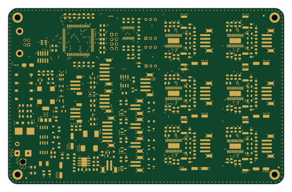
LumenPnP Motherboard
opulo-inc
149 × 95 mm296 parts4LCC-BY-SA-4.03.7k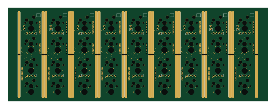 STM32
Main panel
google
234 × 84 mm26 parts4LApache-2.02.9k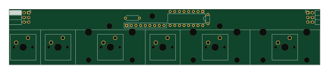 STM32
Type g
169 × 30 mm24 parts2LApache-2.02.9k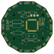 STM32
Base
52.3 × 52.3 mm36 parts2LApache-2.02.9k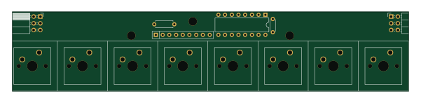 STM32
Type a
150 × 30 mm14 parts2LApache-2.02.9k STM32
Type c
188 × 30 mm17 parts2LApache-2.02.9k