
Puch-Power-Controller-Board

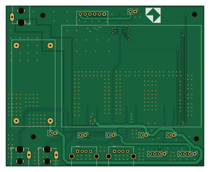
About the Puch-Power-Controller-Board
Puch-Power-Controller-Board is an open source ESP32 PCB design by odelayIO, published on GitHub under the MIT license. It is a 2-layer board measuring 105 × 85 mm, with 45 components from 16 distinct parts.
Its main chip is the MOUDLE-SEEEDUINO-XIAO-ESP32C3, from the ESP32 family. Other key parts include the LM7805_TO220, LM2596_Module and 4-Channel-Relay-Module. By type, the board carries 13 connectors, 12 capacitors, 6 ICs, 6 resistors, 5 transistors and 3 inductors.
It belongs with the iot & wireless designs in this gallery.
From the project
KiCAD 9.0 board design for the puch Power Controller Board
KiCAD 9.0 board design for the puch Power Controller Board. This boad has the following features:
- Create a custom PCB to remotely control the power input for KR260, PYNQ-Z1, and both Pluto SDRs - Single 12VDC power supply will source power to all 4 devices - Add clean external power to both Pluto SDRs (minimum ripple noise) - Add PWM fan controlled by the ESP32 micro-controller to adjust fan speed - Integration to Home Assistant via MQTT device - Utilize already existing parts in my stock :)
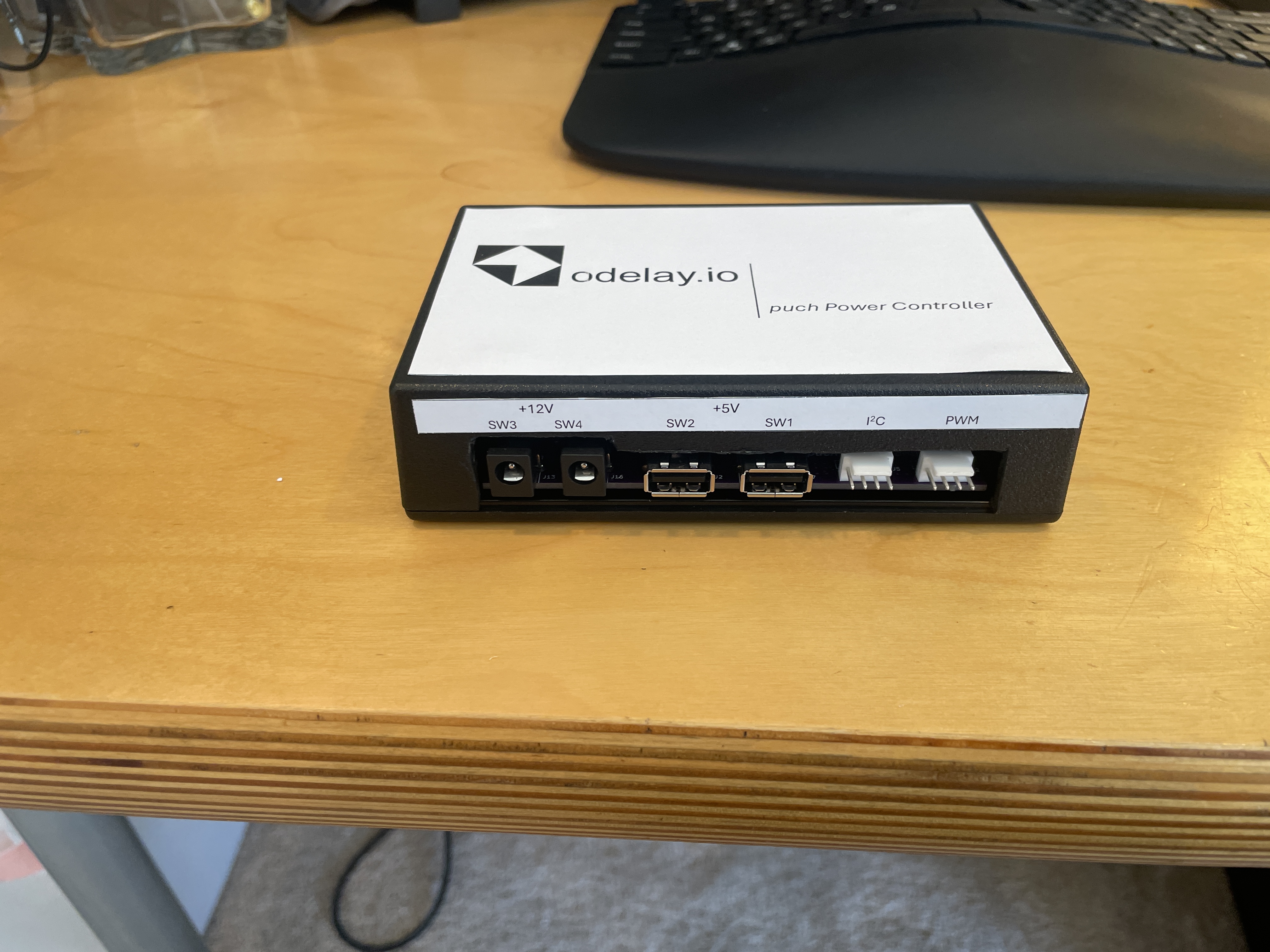
Main components on the Puch-Power-Controller-Board
Puch-Power-Controller-Board bill of materials (BOM)
45 components, 16 distinct parts.
| Qty | Part | Footprint | Refs |
|---|---|---|---|
| 3 | LM7805_TO220 | TO-263-3_TabPin2 | U1, U2, U3 |
| 1 | LM2596_Module | LM2596_Module | U4 |
| 1 | MOUDLE-SEEEDUINO-XIAO-ESP32C3 | MOUDLE14P-SMD-2.54-21X17.8MM | U5 |
| 1 | 4-Channel-Relay-Module | 4-Channel-Relay | U6 |
| 5 | PMBT2222A | SOT-23 | Q1, Q2, Q3, Q4, Q5 |
| 6 | Conn_01x02_Pin | PinHeader_1x02_P2.54mm_Vertical | J1, J3, J4, J6, J14, J17 |
| 2 | USB_A | USB_A_Molex_67643_Horizontal | J2, J7 |
| 2 | Conn_01x04_Pin | PinHeader_1x04_P2.54mm_Vertical | J5, J12 |
| 3 | Barrel_Jack_Switch | BarrelJack_GCT_DCJ200-10-A_Horizontal | J10, J13, J16 |
| 3 | FerriteBead | L_0805_2012Metric | FB1, FB2, FB3 |
| 3 | 0.33uF | C_0805_2012Metric | C1, C5, C9 |
| 3 | 22uF | C_1206_3216Metric | C2, C6, C10 |
| 3 | 0.1uF | C_0805_2012Metric | C3, C7, C11 |
| 3 | 47uF | C_1206_3216Metric | C4, C8, C12 |
| 5 | 1K | R_0805_2012Metric | R1, R2, R3, R4, R5 |
| 1 | 0ohm | R_0805_2012Metric | R9 |
Puch-Power-Controller-Board design files
The KiCad project lives in the odelayIO/puch-Power-Controller-Board repository on GitHub; these links point at the commit this page was built from.
Puch-Power-Controller-Board: common questions
What microcontroller does the Puch-Power-Controller-Board use?
The Puch-Power-Controller-Board is built around the MOUDLE-SEEEDUINO-XIAO-ESP32C3, from the ESP32 family.
How big is the Puch-Power-Controller-Board?
The Puch-Power-Controller-Board measures 105 × 85 mm, has 2 copper layers and is 1.6256 mm thick.
How many components are on the Puch-Power-Controller-Board?
45 components, from 16 distinct parts. The full bill of materials is listed on this page.
Where can I download the Puch-Power-Controller-Board design files?
From the odelayIO/puch-Power-Controller-Board repository on GitHub, which has the KiCad layout and the schematic; the links under Design files point to each one.
Can I use the Puch-Power-Controller-Board design in my own project?
Yes, under the terms of its MIT license, which odelayIO chose for the repository.
Can I test firmware for the Puch-Power-Controller-Board without the hardware?
Yes. HardLabs builds a simulation of the board from its netlist and BOM, so you can run and debug ESP32 firmware against it before you order a PCB.
Similar boards
 ESP32
OSO-BOOK-B1
joeycastillo
85 × 115 mm65 parts2LCC-BY-SA-4.08.1k ESP32
Powertrain
byrantech
64 × 45.4 mm171 parts4LMIT4.3k ESP32
Esp32 minimal
atopile
36.2 × 26.8 mm20 parts2LMIT4.0k ESP32
Badge
56.3 × 39 mm239 parts4LMIT4.0k ESP32
Racer
StuckAtPrototype
36 × 50.2 mm70 parts4LApache-2.03.8k ESP32
Controller
29 × 74 mm58 parts4LApache-2.03.8k