
Camera gpio interface

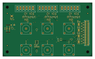
About the Camera gpio interface PCB
Camera gpio interface is an open source PCB design by peterpolidoro, published on GitHub under the CC-BY-SA-4.0 license. It is a 4-layer board measuring 100 × 60 mm, with 151 components from 26 distinct parts.
Other key parts include the USBLC6-2P6, SN74LVC1G125DRYR, SN74LV541ARKSR, SN74LVC2G17DRYR and SN74LVC1G07DRYR. By type, the board carries 85 resistors, 26 ICs, 21 capacitors, 11 connectors and 8 diodes.
It belongs with the test & measurement and dev boards & breakouts designs in this gallery.
From the project
KiCad design and documentation for a passive interface board between three FLIR Blackfly S cameras, a pyControl breakout and a Neuropixels OneBox: screw-terminal camera connectors, BNC inputs and outputs, a 50-pin instrument port, USB power.
Interface board for the three FLIR Blackfly S cameras in the Janelia Dudman lab joystick rig: pluggable screw-terminal camera connectors, two BNC inputs from the pyControl breakout, four 3.3 V BNC outputs to a Neuropixels OneBox, an InstrumentPort-Digital-50 with every camera line tapped, and USB power. No MCU, no firmware, no configuration jumpers.
Status, October 2026: v1.0 is the fabricated revision. Five assembled boards were ordered from JLCPCB on 2026-09-26 (fabrication log), and one is installed in the rig, wired to the three cameras, the pyControl breakout and the OneBox. Bench…
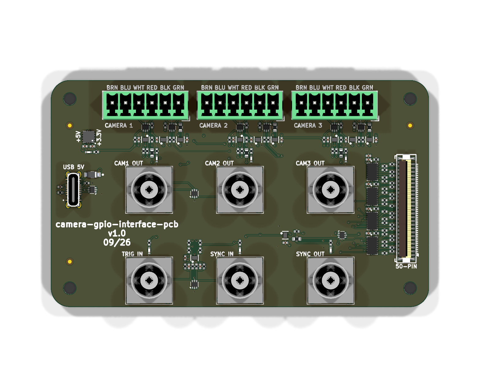
Main components on the Camera gpio interface
Camera gpio interface bill of materials (BOM)
151 components, 26 distinct parts — part numbers from the project's BOM.
| Qty | Part | Footprint | Refs |
|---|---|---|---|
| 10 | USBLC6-2P6 STMicroelectronics | USBLC6-2P6_SOT-666 | U301, U402, U403, U704, U705, U901, U1204, U1205 +2 |
| 4 | SN74LVC1G125DRYR Texas Instruments | DRY6 | U401, U702, U1202, U1402 |
| 4 | SN74LV541ARKSR Texas Instruments | Texas_RKS0020A_VQFN-20-1EP_2.5x4.5mm_P0.5mm_EP1x3mm | U501, U502, U503, U504 |
| 4 | SN74LVC2G17DRYR Texas Instruments | DRY6 | U701, U1101, U1201, U1401 |
| 3 | SN74LVC1G07DRYR Texas Instruments | DRY6 | U703, U1203, U1403 |
| 1 | TPS73733QDRBRQ1 Texas Instruments | TPS737Q1 | U1001 |
| 6 | C19712152 HL-BNC-KHDA Shenzhen HenryTech | CONN_BNC_HL-BNC-KHDA | J301, J302, J401, J402, J403, J404 |
| 1 | C597991 FH12-50S-0.5SVA(54) Hirose Electric | Hirose_FH12-50S-0.5SVA_1x50-4MP_P0.5mm_Vertical | J501 |
| 3 | 1843648 TBH-1x06-3.5mm Phoenix Contact | PhoenixContact_MCV_1,5_6-G-3.5_1x06_P3.50mm_Vertical | J701, J1201, J1401 |
| 1 | USB4145-03-0070-C USB-C Global Connector Technology | USB_C_Receptacle_GCT_USB4145-03-0070-C_16P_Vertical | J901 |
| 7 | APHHS1005CGCK Kingbright | LED_0402-1005_KNB | D201, D301, D302, D401, D701, D1201, D1401 |
| 1 | MBR120VLSFT1G onsemi | SOD-123FL | D901 |
| 16 | GRM155R62A104KE14D 100nF Murata Electronics | C_0402_1005Metric | C401, C502, C503, C504, C505, C701, C702, C703 +8 |
| 1 | GRM155R61E475ME15D 4.7uF Murata Electronics | C_0402_1005Metric | C501 |
| 2 | CL05A105KL5NRNC 1uF Samsung Electro-Mechanics | C_0402_1005Metric | C1001, C1002 |
| 2 | GRM1555C2A471JE01D 470pF Murata Electronics | C_0402_1005Metric | C1101, C1102 |
| 7 | RC0402FR-07680RL 680 YAGEO | R_0402_1005Metric | R201, R301, R302, R401, R706, R1206, R1406 |
| 4 | 0603WAF4700T5E 470 UNI-ROYAL(Uniroyal Elec) | R_0603_1608Metric | R402, R705, R1205, R1405 |
| 50 | 0402WGF1000TCE 100 UNI-ROYAL(Uniroyal Elec) | R_0402_1005Metric | R403, R505, R506, R507, R508, R509, R510, R511 +42 |
| 4 | ERJ2GEJ103X 10k PANASONIC | R_0402_1005Metric | R501, R502, R503, R504 |
Show 6 more
| Qty | Part | Footprint | Refs |
|---|---|---|---|
| 3 | RC0402FR-071KL 1k YAGEO | R_0402_1005Metric | R701, R1201, R1401 |
| 5 | 0402WGF4701TCE 4.7k UNI-ROYAL(Uniroyal Elec) | R_0402_1005Metric | R702, R1103, R1104, R1202, R1402 |
| 3 | FRC0402F8200TS 820 FOJAN | R_0402_1005Metric | R703, R1203, R1403 |
| 3 | 0603WAF2200T5E 220 UNI-ROYAL(Uniroyal Elec) | R_0603_1608Metric | R704, R1204, R1404 |
| 2 | ERJ2GEJ512X 5.1k Panasonic Electronic Components | R_0402_1005Metric | R901, R902 |
| 4 | RC0402JR-07100KL 100k YAGEO | R_0402_1005Metric | R1101, R1102, R1105, R1106 |
Camera gpio interface design files
The KiCad project lives in the peterpolidoro/camera-gpio-interface-pcb repository on GitHub; these links point at the commit this page was built from.
Camera gpio interface: common questions
How big is the Camera gpio interface PCB?
The Camera gpio interface measures 100 × 60 mm, has 4 copper layers and is 1.6 mm thick.
How many components are on the Camera gpio interface?
151 components, from 26 distinct parts, with part numbers taken from the project's own BOM. The full bill of materials is listed on this page.
Where can I download the Camera gpio interface design files?
From the peterpolidoro/camera-gpio-interface-pcb repository on GitHub, which has the KiCad layout, the schematic and the BOM; the links under Design files point to each one.
Can I use the Camera gpio interface design in my own project?
Yes, under the terms of its CC-BY-SA-4.0 license, which peterpolidoro chose for the repository.
Similar boards
AnalyzerBoxPCB fork
gusmanb
52.7 × 47.9 mm54 parts4LGPL-3.05.0k
LevelShifter
28.3 × 39.8 mm21 parts2LGPL-3.05.0k
StackLink
52.3 × 10.5 mm5 parts2LGPL-3.05.0k
Breakout 60pin EEC-IV
rusefi
139.7 × 62.2 mm15 parts2LGPL-3.01.2k
88 Pin Vag Breakout
142 × 58 mm91 parts2LGPL-3.01.2k
Eecv breakout
140.8 × 53.7 mm9 parts4LGPL-3.01.2k