
Relaymux

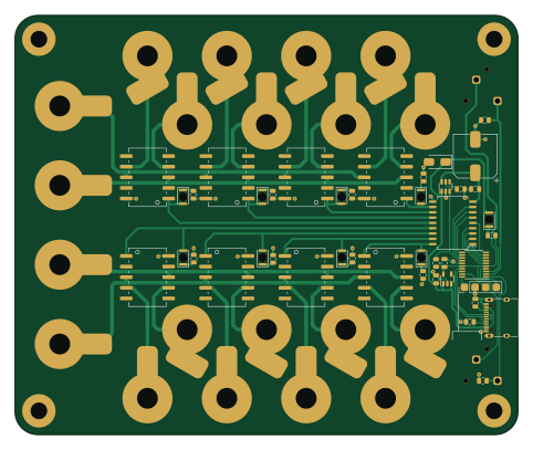
About the Relaymux PCB
Relaymux is an open source STM32 PCB design by PetteriAimonen, published on GitHub under the BSD-2-Clause license. It is a 2-layer board measuring 120.4 × 100.4 mm, with 55 components from 26 distinct parts.
Its main chip is the STM32F042F6P6, from the STM32 family. Other key parts include the TBD62783AFG,EL, TPS2552DBVR and TLV70033DDCR. By type, the board carries 15 resistors, 12 connectors, 10 diodes, 8 relays, 4 ICs and 4 capacitors.
It belongs with the test & measurement designs in this gallery.
From the project
Hardware and firmware for a USB connected relay box
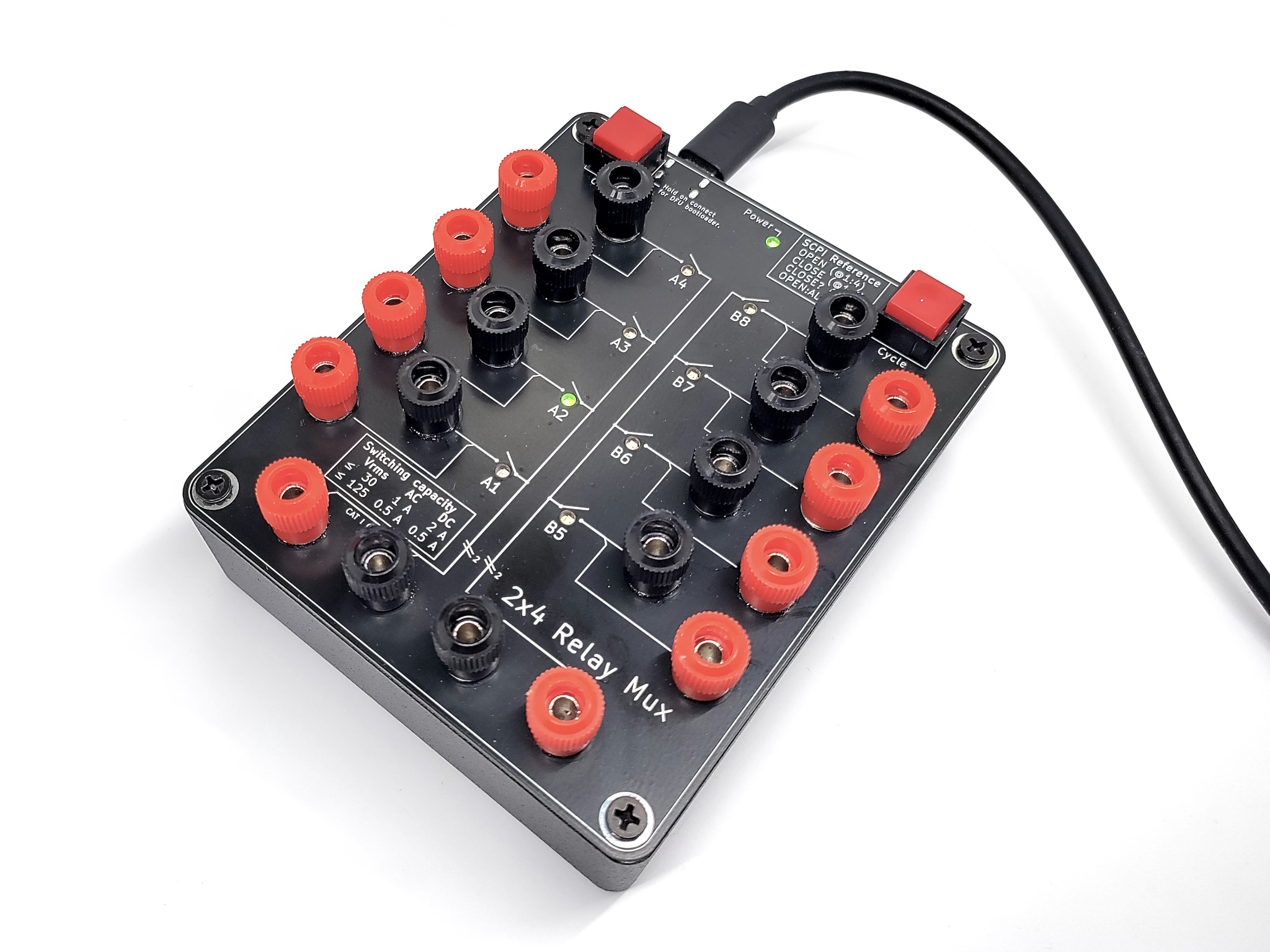
This repository contains hardware and firmware for a USB Relay Mux that has two independent halves, each of which multiplexes a pair of signals to four channels. It is designed for use in automatic testing, for example to switch input signals to multimeter or to change polarity of a power supply.
[](images/relaymux1.jpg) [](images/relaymux2.jpg)
Many of the cheap USB relay boards are designed for switching large currents, and not for lab usage. They have several shortcomings:
Main components on the Relaymux
Relaymux bill of materials (BOM)
55 components, 26 distinct parts — part numbers from the project's BOM.
| Qty | Part | Footprint | Refs |
|---|---|---|---|
| 1 | STM32F042F6P6 STM32F042F6Px | TSSOP-20_4.4x6.5mm_P0.65mm | U1 |
| 1 | TBD62783AFG,EL TBD62783A | SOP-18_7x12.5mm_P1.27mm | U2 |
| 1 | TPS2552DBVR TPS2552D | SOT-23-6 | U3 |
| 1 | TLV70033DDCR TLV70033_SOT23-5 | SOT-23-5 | U4 |
| 1 | A | Binding_Post_Pair | J1 |
| 1 | A1 | Binding_Post_Pair_120deg | J2 |
| 1 | A2 | Binding_Post_Pair_120deg | J3 |
| 1 | A3 | Binding_Post_Pair_120deg | J4 |
| 1 | A4 | Binding_Post_Pair_120deg | J5 |
| 1 | B | Binding_Post_Pair | J6 |
| 1 | B1 | Binding_Post_Pair_60deg | J7 |
| 1 | B2 | Binding_Post_Pair_60deg | J8 |
| 1 | B3 | Binding_Post_Pair_60deg | J9 |
| 1 | B4 | Binding_Post_Pair_60deg | J10 |
| 1 | U262-161N-4BVC11 USB_C | USB_C_Receptacle_XKB_U262-16XN-4BVC11 | J11 |
| 1 | Debug | Pads_1x04_P2.54mm_Vertical | J12 |
| 8 | TQ2SA-5V | Relay_TQ2SA | K1, K2, K3, K4, K5, K6, K7, K8 |
| 1 | 320E11BLK Cycle | SW_320E11 | SW1 |
| 1 | 320E11BLK Boot/Clear | SW_320E11 | SW2 |
| 9 | LTST-C230KGKT LED | LED_LTST-C230 | D1, D2, D3, D4, D5, D6, D7, D8 +1 |
Show 6 more
| Qty | Part | Footprint | Refs |
|---|---|---|---|
| 1 | SMAJ5.0A | D_SMA | D9 |
| 3 | CL21A106KAYNNNE 10µF | C_0805_2012Metric | C1, C3, C4 |
| 1 | UWD1E471MCL1GS 470µF | CP_Elec_10x10 | C5 |
| 9 | Generic 470 | R_0805_2012Metric | R1, R2, R3, R4, R5, R6, R7, R8 +1 |
| 2 | Generic 5k1 | R_0805_2012Metric | R9, R10 |
| 4 | Generic 68k | R_0805_2012Metric | R11, R12, R14, R15 |
Relaymux design files
The KiCad project lives in the PetteriAimonen/relaymux repository on GitHub; these links point at the commit this page was built from.
- Layoutpcb/relaymux.kicad_pcb
- Schematicpcb/relaymux.kicad_sch
- BOMpcb/gerbers/bom-generic.csv
Relaymux: common questions
What microcontroller does the Relaymux use?
The Relaymux is built around the STM32F042F6P6, from the STM32 family.
How big is the Relaymux PCB?
The Relaymux measures 120.4 × 100.4 mm, has 2 copper layers and is 1.6 mm thick.
How many components are on the Relaymux?
55 components, from 26 distinct parts, with part numbers taken from the project's own BOM. The full bill of materials is listed on this page.
Where can I download the Relaymux design files?
From the PetteriAimonen/relaymux repository on GitHub, which has the KiCad layout, the schematic and the BOM; the links under Design files point to each one.
Can I use the Relaymux design in my own project?
Yes, under the terms of its BSD-2-Clause license, which PetteriAimonen chose for the repository.
Can I test firmware for the Relaymux without the hardware?
Yes. HardLabs builds a simulation of the board from its netlist and BOM, so you can run and debug STM32 firmware against it before you order a PCB.
Similar boards
 STM32
STM32LumenPnP Motherboard
opulo-inc
149 × 95 mm296 parts4LCC-BY-SA-4.03.7k STM32
STM32AxxSolder
AxxAxx
39 × 82.5 mm122 parts2LGPL-3.01.7k STM32
STM32AIOC
skuep
21 × 31.5 mm47 parts2LMIT1.4k STM32
STM32Ferris
pierrechevalier83
208.8 × 86.8 mm102 parts2LSHL-2.11.3k STM32
STM32Module 16S
stuartpittaway
71.1 × 89.6 mm113 parts4LCC-BY-NC-4.01.1k STM32
STM32Djinn
tzarc
192.3 × 150.5 mm216 parts2LCERN-OHL-S-2.0988