
Input Signal Conditioner (ISC)

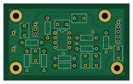
About the Input Signal Conditioner (ISC) PCB
Input Signal Conditioner (ISC) is an open source PCB design by piercehowell, published on GitHub under the MIT license. It is a 2-layer board measuring 65.4 × 40 mm, with 21 components from 19 distinct parts.
Other key parts include the MCP6272. By type, the board carries 9 resistors, 7 capacitors, 4 connectors and 1 IC.
It belongs with the audio designs in this gallery.
From the project
Digital vocal effect processor "stompbox" that applies a variety of real-time signal processing algorithms to alther the voice of a singer.
Here is how to create a new branch off of main. Please use the following naming format for the branch [Yourname][descriptionofbranch]
Main components on the Input Signal Conditioner (ISC)
Input Signal Conditioner (ISC) bill of materials (BOM)
21 components, 19 distinct parts — part numbers from the project's BOM.
| Qty | Part | Footprint | Refs |
|---|---|---|---|
| 1 | MCP6272 | DIP-8_W7.62mm | U1 |
| 2 | Conn_01x01 | PinSocket_1x01_P2.54mm_Vertical | J1, J2 |
| 1 | Conn_01x05 | PinSocket_1x05_P2.54mm_Vertical | J3 |
| 1 | Conn_01x03 | PinSocket_1x03_P2.54mm_Vertical | J4 |
| 1 | 22NF 220n | C_Disc_D7.5mm_W4.4mm_P5.00mm | C1 |
| 1 | 4.7NF 4.7n | C_Disc_D7.5mm_W4.4mm_P5.00mm | C2 |
| 1 | 4.7UF 4.7u | C_Disc_D7.5mm_W4.4mm_P5.00mm | C3 |
| 1 | 100NF 680p | C_Disc_D7.5mm_W4.4mm_P5.00mm | C4 |
| 1 | 680PF 1.5n | C_Disc_D7.5mm_W4.4mm_P5.00mm | C5 |
| 1 | 1.5NF 0.1u | C_Disc_D7.5mm_W4.4mm_P5.00mm | C6 |
| 1 | 3.3UF 0.1u | C_Disc_D7.5mm_W4.4mm_P5.00mm | C7 |
| 2 | 50K | R_Axial_DIN0207_L6.3mm_D2.5mm_P10.16mm_Horizontal | R1, R2 |
| 1 | 100K | R_Axial_DIN0207_L6.3mm_D2.5mm_P10.16mm_Horizontal | R3 |
| 1 | 1K | R_Axial_DIN0207_L6.3mm_D2.5mm_P10.16mm_Horizontal | R4 |
| 1 | 11K | R_Axial_DIN0207_L6.3mm_D2.5mm_P10.16mm_Horizontal | R5 |
| 1 | 11.25K | R_Axial_DIN0207_L6.3mm_D2.5mm_P10.16mm_Horizontal | R6 |
| 1 | 14.3K | R_Axial_DIN0207_L6.3mm_D2.5mm_P10.16mm_Horizontal | R7 |
| 1 | 0 | R_Axial_DIN0207_L6.3mm_D2.5mm_P10.16mm_Horizontal | R8 |
| 1 | INF | R_Axial_DIN0207_L6.3mm_D2.5mm_P10.16mm_Horizontal | R9 |
Input Signal Conditioner (ISC) design files
The KiCad project lives in the piercehowell/DIGIMUSER repository on GitHub; these links point at the commit this page was built from.
Input Signal Conditioner (ISC): common questions
How big is the Input Signal Conditioner (ISC) PCB?
The Input Signal Conditioner (ISC) measures 65.4 × 40 mm, has 2 copper layers and is 1.6 mm thick.
How many components are on the Input Signal Conditioner (ISC)?
21 components, from 19 distinct parts, with part numbers taken from the project's own BOM. The full bill of materials is listed on this page.
Where can I download the Input Signal Conditioner (ISC) design files?
From the piercehowell/DIGIMUSER repository on GitHub, which has the KiCad layout and the BOM; the links under Design files point to each one.
Can I use the Input Signal Conditioner (ISC) design in my own project?
Yes, under the terms of its MIT license, which piercehowell chose for the repository.
More boards in DIGIMUSER

Similar boards
KLOR
GEIGEIGEIST
160.2 × 118.3 mm79 parts2LGPL-3.01.2k
ButtonsLEDs
shanteacontrols
390 × 37 mm82 parts2LApache-2.0956
USB
52 × 12.6 mm6 parts2LApache-2.0956
Pots
390 × 93 mm75 parts2LApache-2.0956
PicoGUS Hand386
polpo
29.2 × 75.2 mm43 parts4LGPL-2.0800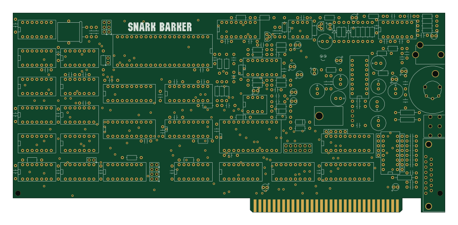
Snark barker
schlae
231.1 × 106.7 mm193 parts2LNo license687