
C64-RF-Modulator

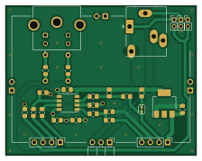
About the C64-RF-Modulator PCB
C64-RF-Modulator is an open source PCB design by pmandes, published on GitHub under the MIT license. It is a 2-layer board measuring 55.9 × 43.9 mm, with 34 components from 19 distinct parts.
By type, the board carries 11 resistors, 5 capacitors, 4 inductors, 3 connectors, 1 switch and 1 LED.
It belongs with the retro computing and audio designs in this gallery.
From the project
Commodore C64C RF modulator replacement with S-Video and stereo audio output.
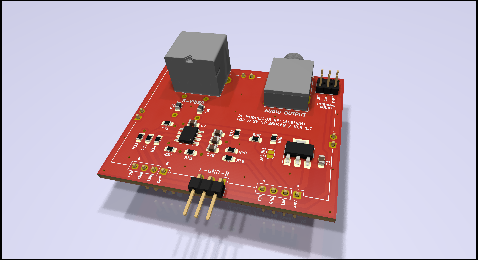
This is a project of a modulator replacement based on an analog c0pperdragon module. It was adjusted in size to the Commodore C64C motherboard and extended with S-Video and Strereo Audio outputs.
1.2 - internal audio route to left and/or right channel - ferrite beads to suppresses high-frequency electronic noise - silkscreen layer with descriptions of all outputs and elements - 3D models for a nice rendering - project cleaned up and migrated to KiCad 6.0 - interactive BOM
C64-RF-Modulator bill of materials (BOM)
34 components, 19 distinct parts.
| Qty | Part | Footprint | Refs |
|---|---|---|---|
| 3 | Conn_01x02 | PinHeader_1x02_P2.00mm_Vertical | J1, J2, J3 |
| 1 | Conn_01x03 | PinHeader_1x03_P2.54mm_Horizontal | AUDIO_OUT1 |
| 3 | Conn_01x02 | PinHeader_1x02_P2.54mm_Vertical | GND1, GND2, GND3 |
| 1 | Jumper_2_Open | SolderJumper-2_P1.3mm_Open_RoundedPad1.0x1.5mm | JPLUM1 |
| 1 | LM1117-3.3 | SOT-223 | LM1117-3.3 |
| 2 | Conn_01x04 | PinHeader_1x04_P2.54mm_Vertical | RFCONC1, RFCONC2 |
| 1 | Mini-DIN-4 | TE_5749181-1 | S-VIDEO1 |
| 1 | THS7316 | SSOP-8_3.95x5.21x3.27mm_P1.27mm | THS7316 |
| 1 | AudioJack2_Ground | Jack_3.5mm_Ledino_KB3SPRS_Horizontal | STEREO_OUT1 |
| 2 | Ferrite Bead | L_0805_2012Metric_Pad1.15x1.40mm_HandSolder | FB1, FB2 |
| 2 | 81-BL02RN1R2M2 | R_Axial_DIN0207_L6.3mm_D2.5mm_P7.62mm_Horizontal | FB3, FB4 |
| 2 | 10uF | C_0805_2012Metric_Pad1.18x1.45mm_HandSolder | C1, C9 |
| 3 | 100nF | C_0805_2012Metric_Pad1.18x1.45mm_HandSolder | C10, C28, C29 |
| 1 | 3k3 | R_0805_2012Metric_Pad1.20x1.40mm_HandSolder | R30 |
| 1 | 1k | R_0805_2012Metric_Pad1.20x1.40mm_HandSolder | R31 |
| 1 | 2k2 | R_0805_2012Metric_Pad1.20x1.40mm_HandSolder | R32 |
| 3 | 75 | R_0805_2012Metric_Pad1.20x1.40mm_HandSolder | R33, R34, R35 |
| 3 | 680 | R_0805_2012Metric_Pad1.20x1.40mm_HandSolder | R36, R38, R39 |
| 2 | 330 | R_0805_2012Metric_Pad1.20x1.40mm_HandSolder | R37, R40 |
C64-RF-Modulator design files
The KiCad project lives in the pmandes/C64-RF-Modulator repository on GitHub; these links point at the commit this page was built from.
C64-RF-Modulator: common questions
How big is the C64-RF-Modulator PCB?
The C64-RF-Modulator measures 55.9 × 43.9 mm, has 2 copper layers and is 1.6 mm thick.
How many components are on the C64-RF-Modulator?
34 components, from 19 distinct parts. The full bill of materials is listed on this page.
Where can I download the C64-RF-Modulator design files?
From the pmandes/C64-RF-Modulator repository on GitHub, which has the KiCad layout and the schematic; the links under Design files point to each one.
Can I use the C64-RF-Modulator design in my own project?
Yes, under the terms of its MIT license, which pmandes chose for the repository.
Similar boards
KLOR
GEIGEIGEIST
160.2 × 118.3 mm79 parts2LGPL-3.01.2k
ButtonsLEDs
shanteacontrols
390 × 37 mm82 parts2LApache-2.0956
USB
52 × 12.6 mm6 parts2LApache-2.0956
Pots
390 × 93 mm75 parts2LApache-2.0956
OpenTendo
Redherring32
196.3 × 118.7 mm93 parts2LTAPR-OHL-1.0850
PicoGUS Hand386
polpo
29.2 × 75.2 mm43 parts4LGPL-2.0800