
STM32F4-Test-Board

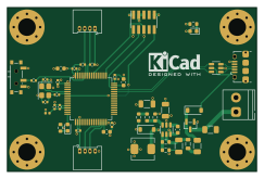
About the STM32F4-Test-Board
STM32F4-Test-Board is an open source STM32 PCB design by pravinsharma15k-ops, published on GitHub. It is a 4-layer board measuring 60.7 × 40 mm, with 46 components from 35 distinct parts.
Its main chip is the STM32F405RGT6, from the STM32 family. Other key parts include the MP2359DJ-LF-Z and USBLC6-2SC6. By type, the board carries 16 capacitors, 11 resistors, 5 connectors, 4 diodes, 3 ICs and 3 inductors.
It belongs with the power & battery designs in this gallery.
From the project
STM32F405-based test board designed in KiCad 10, with buck converter, USB, SWD, I2C and UART.
A compact STM32F405-based development board designed in KiCad 10. It has a 12 V screw-terminal power input, an on-board buck converter, USB micro-B, and standard debug and communication headers (SWD, I2C, UART).
- MCU: STM32F405RGT6 (ARM Cortex-M4, LQFP-64), 16 MHz crystal - Power input: 12 V via 2-pin screw terminal, protected by a 250 mA fuse - Buck converter: MP2359DJ-LF-Z (adjustable, feedback resistor divider) - USB: micro-B connector with USBLC6-2SC6 ESD protection - Programming and debug: 10-pin SWD header (SWCLK, SWDIO, SWO, NRST) - Communication: I2C1 header (with 2.2 kOhm pull-ups)…
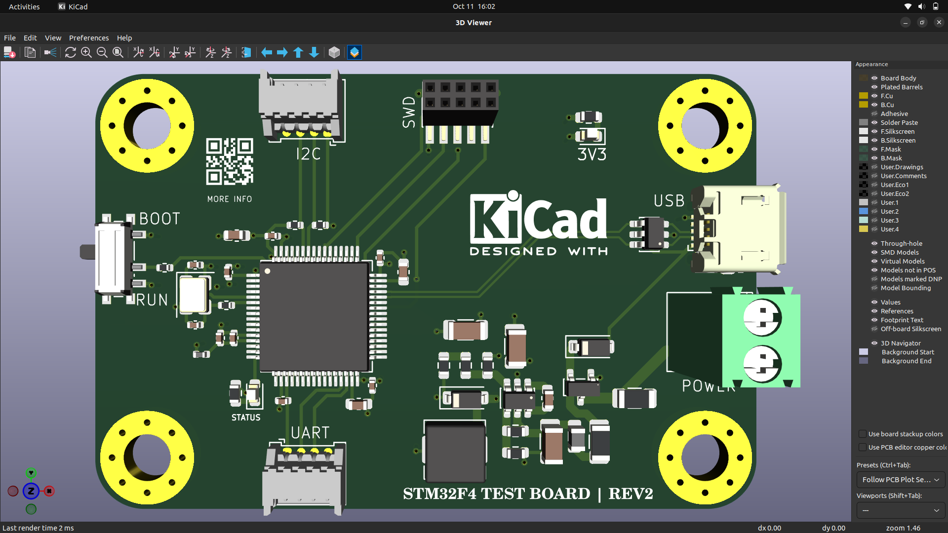
Main components on the STM32F4-Test-Board
STM32F4-Test-Board bill of materials (BOM)
46 components, 35 distinct parts — part numbers from the project's BOM.
| Qty | Part | Footprint | Refs |
|---|---|---|---|
| 1 | MP2359DJ-LF-Z | SOT-23-6 | U1 |
| 1 | STM32F405RGT6 | LQFP-64_10x10mm_P0.5mm | U2 |
| 1 | USBLC6-2SC6 | SOT-23-6 | U3 |
| 1 | AO3401A | SOT-23 | Q1 |
| 1 | 16MHz | Crystal_SMD_3225-4Pin_3.2x2.5mm | Y1 |
| 1 | Screw_Terminal_01x02 | TerminalBlock_Phoenix_PT-1,5-2-3.5-H_1x02_P3.50mm_Horizontal | J1 |
| 1 | SWD | PinSocket_2x05_P1.27mm_Vertical_SMD | J2 |
| 2 | Conn_01x04 | Molex_PicoBlade_53048-0410_1x04_P1.25mm_Horizontal | J3, J4 |
| 1 | USB_B_Micro | USB_Micro-B_Amphenol_10118194_Horizontal | J6 |
| 1 | 250mA | Fuse_1206_3216Metric | F1 |
| 1 | SW_SPDT | SW_SPDT_PCM12 | SW1 |
| 2 | B5819W | D_SOD-123 | D1, D2 |
| 1 | RED | LED_0603_1608Metric | D3 |
| 1 | BLUE | LED_0603_1608Metric | D4 |
| 1 | 600@ 600MHz | L_0805_2012Metric | FB1 |
| 1 | 10u | L_Sunlord_MWSA0518S | L1 |
| 1 | 39n | L_0402_1005Metric | L2 |
| 3 | 10u | C_1206_3216Metric | C1, C2, C3 |
| 1 | 10n | C_0603_1608Metric | C4 |
| 1 | 4u7 | C_0603_1608Metric | C5 |
Show 15 more
| Qty | Part | Footprint | Refs |
|---|---|---|---|
| 5 | 100n | C_0402_1005Metric | C6, C7, C8, C9, C10 |
| 1 | 1u | C_0402_1005Metric | C11 |
| 1 | 10n | C_0402_1005Metric | C12 |
| 2 | 2u2 | C_0603_1608Metric | C13, C14 |
| 2 | 12p | C_0402_1005Metric | C15, C16 |
| 1 | 100k | R_0603_1608Metric | R1 |
| 1 | 68k | R_0603_1608Metric | R2 |
| 1 | 47k | R_0603_1608Metric | R3 |
| 1 | 15k | R_0603_1608Metric | R4 |
| 1 | 270 | R_0603_1608Metric | R5 |
| 1 | 1k | R_0603_1608Metric | R6 |
| 1 | 10k | R_0402_1005Metric | R7 |
| 1 | 47 | R_0402_1005Metric | R8 |
| 1 | 1k5 | R_0603_1608Metric | R9 |
| 2 | 2k2 | R_0402_1005Metric | R10, R11 |
STM32F4-Test-Board design files
The KiCad project lives in the pravinsharma15k-ops/STM32F4-Test-Board repository on GitHub; these links point at the commit this page was built from.
STM32F4-Test-Board: common questions
What microcontroller does the STM32F4-Test-Board use?
The STM32F4-Test-Board is built around the STM32F405RGT6, from the STM32 family.
How big is the STM32F4-Test-Board?
The STM32F4-Test-Board measures 60.7 × 40 mm, has 4 copper layers and is 1.6 mm thick.
How many components are on the STM32F4-Test-Board?
46 components, from 35 distinct parts, with part numbers taken from the project's own BOM. The full bill of materials is listed on this page.
Where can I download the STM32F4-Test-Board design files?
From the pravinsharma15k-ops/STM32F4-Test-Board repository on GitHub, which has the KiCad layout, the schematic and the BOM; the links under Design files point to each one.
Can I use the STM32F4-Test-Board design in my own project?
The repository has no license, so all rights stay with pravinsharma15k-ops. Use it as a reference, and ask the author before reusing the design.
Can I test firmware for the STM32F4-Test-Board without the hardware?
Yes. HardLabs builds a simulation of the board from its netlist and BOM, so you can run and debug STM32 firmware against it before you order a PCB.
Similar boards
 STM32
LumenPnP Motherboard
opulo-inc
149 × 95 mm296 parts4LCC-BY-SA-4.03.7k STM32
Type g
google
169 × 30 mm24 parts2LApache-2.02.9k STM32
Base
52.3 × 52.3 mm36 parts2LApache-2.02.9k STM32
Main panel
234 × 84 mm26 parts4LApache-2.02.9k STM32
Type a
150 × 30 mm14 parts2LApache-2.02.9k STM32
Type c
188 × 30 mm17 parts2LApache-2.02.9k