
PTR arecorder

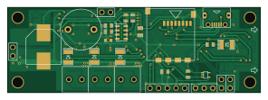
About the PTR arecorder PCB
PTR arecorder is an open source PIC PCB design by PTR-projects, published on GitHub under the MIT license. It is a 2-layer board measuring 74 × 25 mm, with 83 components from 39 distinct parts.
Its main chip is the PIC24FJ128GB206, from the PIC family. Other key parts include the SD_CARD, MMA6519, LIS331HH, STLM20W87 and MPL3115A2. By type, the board carries 24 resistors, 19 capacitors, 10 connectors, 8 ICs, 8 transistors and 8 diodes.
It belongs with the sensors designs in this gallery.
From the project
Version: v2.2 (PTR edition) Maintained by: bartekM
Version: v2.2 (PTR edition) Maintained by: bartekM
A compact, high-g flight data recorder designed specifically for model and amateur rocketry. The Arecorder logs 3-axis acceleration and orientation data to an SD card during launch, ascent, apogee, and recovery. Developed and used by the Polskie Towarzystwo Rakietowe (PTR) – the Polish Rocketry Society.
This repository contains all design files needed to build your own Arecorder: KiCad schematics & PCB layout, Gerber files, Bill of Materials (BOM), assembly notes, and firmware source code.
Main components on the PTR arecorder
PTR arecorder bill of materials (BOM)
83 components, 39 distinct parts.
| Qty | Part | Footprint | Refs |
|---|---|---|---|
| 1 | SD_CARD | MICRO_SD_CARD_SLOT | U1 |
| 1 | PIC24FJ128GB206 | TQFP_64 | U2 |
| 1 | MMA6519 | QFN16 | U3 |
| 1 | LIS331HH | LGA16 | U4 |
| 1 | STLM20W87 | SOT323-5L | U5 |
| 1 | MPL3115A2 | LGA8_3x5 | U6 |
| 2 | TPS76333 | SOT23-5 | U7, U8 |
| 4 | HOLE | HOLE_3mm | A1, A2, A3, A4 |
| 8 | PMV20XN | SOT23GDS | Q1, Q2, Q3, Q4, Q5, Q6, Q7, Q8 |
| 1 | 16 MHz | HC-3.4x2.7 | X1 |
| 1 | USB_B_micro | USB_MICRO | J1 |
| 1 | PROG | conn_goldpin_5 | P1 |
| 1 | UART | conn_goldpin_3 | P2 |
| 1 | CONF_SEL1 | conn_goldpin_2 | P3 |
| 1 | CONF_SEL2 | conn_goldpin_2 | P4 |
| 1 | OUT1 | conn_ark_2_3.81 | P5 |
| 1 | OUT2 | conn_ark_2_3.81 | P6 |
| 1 | OUT3 | conn_ark_2_3.81 | P7 |
| 1 | EXT_BUZZER | conn_goldpin_2 | P8 |
| 1 | POWER | conn_goldpin_2 | P9 |
Show 19 more
| Qty | Part | Footprint | Refs |
|---|---|---|---|
| 1 | SPEAKER | buzzer_12mm | SP1 |
| 1 | LED ORANGE | SM1210_DIODE | D1 |
| 3 | LED RED | SM1210_DIODE | D2, D3, D4 |
| 3 | 1N4148 | SM0805_DIODE | D5, D6, D8 |
| 1 | LL103C | SM1206_DIODE | D7 |
| 4 | 10u | SM0805 | C1, C2, C18, C19 |
| 2 | 18p | SM0603 | C3, C4 |
| 8 | 100n | SM0603 | C5, C6, C7, C8, C11, C12, C15, C16 |
| 3 | 1u | SM0603 | C9, C10, C14 |
| 1 | 1u | C_0603_1608Metric | C13 |
| 1 | 1mF/10V | SMD_G_cap | C17 |
| 10 | 1k | SM0603 | R1, R2, R7, R9, R11, R12, R15, R16 +2 |
| 8 | 10k | SM0603 | R3, R8, R10, R13, R14, R17, R18, R20 |
| 1 | 470R | SM0603 | R4 |
| 1 | 100k | SM0603 | R5 |
| 1 | 100R | SM0603 | R6 |
| 1 | 10R | SM0603 | R22 |
| 1 | 100k/1% | SM0603 | R23 |
| 1 | 47k/1% | SM0603 | R24 |
PTR arecorder design files
The KiCad project lives in the PTR-projects/PTR_arecorder repository on GitHub; these links point at the commit this page was built from.
PTR arecorder: common questions
What microcontroller does the PTR arecorder use?
The PTR arecorder is built around the PIC24FJ128GB206, from the PIC family.
How big is the PTR arecorder PCB?
The PTR arecorder measures 74 × 25 mm, has 2 copper layers and is 1.6002 mm thick.
How many components are on the PTR arecorder?
83 components, from 39 distinct parts. The full bill of materials is listed on this page.
Where can I download the PTR arecorder design files?
From the PTR-projects/PTR_arecorder repository on GitHub, which has the KiCad layout; the links under Design files point to each one.
Can I use the PTR arecorder design in my own project?
Yes, under the terms of its MIT license, which PTR-projects chose for the repository.
Can I test firmware for the PTR arecorder without the hardware?
Yes. HardLabs builds a simulation of the board from its netlist and BOM, so you can run and debug PIC firmware against it before you order a PCB.
Similar boards
 PIC
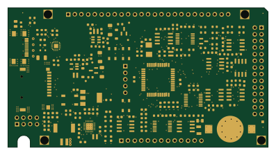
PICPslab hardware
fossasia
99 × 53.3 mm187 parts4LApache-2.01.7k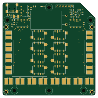 PIC
PICLens
ervanalb
80 × 80 mm53 parts4LNo license515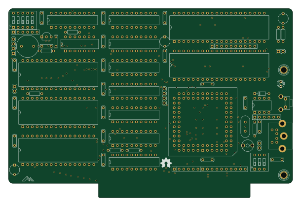 PIC
PICMicro 8088
skiselev
152.4 × 101.6 mm71 partsGPL-3.0414 PIC
PICGB-LIVE32
Gekkio
51.4 × 61 mm46 parts4LCC-BY-4.0376 PIC
PICGB-MBCTEST
51.4 × 61 mm32 parts2LCC-BY-4.0376 PIC
PICGB-BENCH-G1
100 × 100 mm98 parts4LCC-BY-4.0376