
Adjustable-DC-DC-Step-Down-Converter

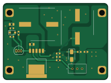
About the Adjustable-DC-DC-Step-Down-Converter PCB
Adjustable-DC-DC-Step-Down-Converter is an open source PCB design by raju-gudala, published on GitHub. It is a 2-layer board measuring 55 × 40 mm, with 21 components from 20 distinct parts.
Other key parts include the LM2596S-ADJ/NOPB. By type, the board carries 6 capacitors, 5 resistors, 4 connectors, 2 diodes, 1 IC and 1 transistor.
It belongs with the power & battery designs in this gallery.
From the project
Adjustable DC-DC buck converter using LM2596S-ADJ, converting 5V–40V DC to a regulated output up to 3A.
This project demonstrates the design and implementation of an adjustable DC-DC buck converter using the LM2596S-ADJ IC. The converter accepts a wide input range of 4.5–40V DC and delivers a regulated, adjustable output capable of supplying up to 3A continuous current.
- Complete schematic design in KiCad - LTspice simulation for stability and performance verification - Optimized PCB layout for high efficiency and low output ripple - Power stage, feedback network, and input/output filtering included - Reliable voltage regulation using feedback compensation techniques
Main components on the Adjustable-DC-DC-Step-Down-Converter
Adjustable-DC-DC-Step-Down-Converter bill of materials (BOM)
21 components, 20 distinct parts.
| Qty | Part | Footprint | Refs |
|---|---|---|---|
| 1 | LM2596S-ADJ/NOPB LM2596S-ADJ_NOPB | LM2596SXADJ | IC1 |
| 1 | 2N3904 | TO-92_Inline | Q1 |
| 1 | Vin+ | SolderWire-2.5sqmm_1x01_D2.4mm_OD4.4mm | J1 |
| 1 | Vin- | SolderWire-2.5sqmm_1x01_D2.4mm_OD4.4mm | J2 |
| 1 | OUT+ | SolderWire-2.5sqmm_1x01_D2.4mm_OD4.4mm | J3 |
| 1 | OUT- | SolderWire-2.5sqmm_1x01_D2.4mm_OD4.4mm | J4 |
| 1 | 3296W-1-103LF | 3296W1503LF | VR1 |
| 1 | BZT52C5V1 | D_SOD-123F | D1 |
| 1 | SS36 | D_SMA | D2 |
| 1 | 68uH | L_0603_1608Metric | L1 |
| 1 | EEV-TG1H681UM | CAPAE1700X1700N | C1 |
| 1 | 100nF | C_0805_2012Metric | C2 |
| 1 | 1uF | C_0805_2012Metric | C3 |
| 1 | 470pF | C_0603_1608Metric | C4 |
| 1 | 100nF | C_0603_1608Metric | C5 |
| 1 | EEE-FK1H471AM UCZ1H471MNQ1MS | CAPAE1710X1750N | C6 |
| 2 | 10k | R_0603_1608Metric | R1, R2 |
| 1 | 47k | R_0603_1608Metric | R3 |
| 1 | 1k | R_0603_1608Metric | R5 |
| 1 | 1.69k | R_0603_1608Metric | R6 |
Adjustable-DC-DC-Step-Down-Converter design files
The KiCad project lives in the raju-gudala/Adjustable-DC-DC-Step-Down-Converter repository on GitHub; these links point at the commit this page was built from.
Adjustable-DC-DC-Step-Down-Converter: common questions
How big is the Adjustable-DC-DC-Step-Down-Converter PCB?
The Adjustable-DC-DC-Step-Down-Converter measures 55 × 40 mm, has 2 copper layers and is 1.6 mm thick.
How many components are on the Adjustable-DC-DC-Step-Down-Converter?
21 components, from 20 distinct parts. The full bill of materials is listed on this page.
Where can I download the Adjustable-DC-DC-Step-Down-Converter design files?
From the raju-gudala/Adjustable-DC-DC-Step-Down-Converter repository on GitHub, which has the KiCad layout and the schematic; the links under Design files point to each one.
Can I use the Adjustable-DC-DC-Step-Down-Converter design in my own project?
The repository has no license, so all rights stay with raju-gudala. Use it as a reference, and ask the author before reusing the design.
Similar boards

Stack chan
stack-chan
50 × 50 mm33 parts2LApache-2.01.7k
Display Carrier
AxxAxx
35.6 × 58.2 mm5 parts2LGPL-3.01.7k
ControllerCurrentShuntAddOn
stuartpittaway
26 × 16.9 mm9 parts2LCC-BY-NC-4.01.1k
Module 16S PassiveBalanceAddOn
61 × 74 mm86 parts2LCC-BY-NC-4.01.1k
TemperaturePCB PANEL
116 × 75.5 mm178 parts2LCC-BY-NC-4.01.1k
ProgrammingAdapter
10.5 × 83 mm3 parts2LCC-BY-NC-4.01.1k