
Digital-DC-Load

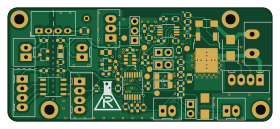
About the Digital-DC-Load PCB
Digital-DC-Load is an open source PCB design by RedlabsDE, published on GitHub. It is a 2-layer board measuring 70 × 30 mm, with 66 components from 35 distinct parts.
Other key parts include the ADuM1250, AM1S-0505, MCP3428, MCP4726 and REF3020. By type, the board carries 22 resistors, 16 capacitors, 9 connectors, 6 ICs, 5 diodes and 4 jumpers.
It belongs with the power & battery designs in this gallery.
From the project
key features: - linear constant curren sink - galvanic isolated - selectable operating range (high/low current/voltage) - controlled via I2C - write & read load current - read load voltage - read additional external voltage - read temperature - manual option: set current via exte
key features: - linear constant curren sink - galvanic isolated - selectable operating range (high/low current/voltage) - controlled via I2C - write & read load current - read load voltage - read additional external voltage - read temperature - manual option: set current via external voltage (or potentiometer)
example application: - charge / discharge battery (control & measure current and voltage) - measure & log current/voltage (use example setup to send data to PC) - stess test of power supply
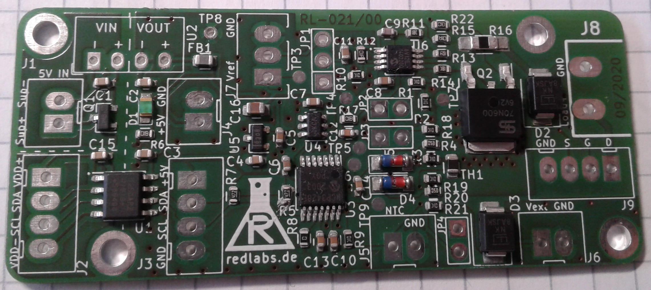
Main components on the Digital-DC-Load
Digital-DC-Load bill of materials (BOM)
66 components, 35 distinct parts.
| Qty | Part | Footprint | Refs |
|---|---|---|---|
| 1 | ADuM1250 | SOIC-8_3.9x4.9mm_Pitch1.27mm | U1 |
| 1 | AM1S-0505 | DCDC-Isolated-SIP4 | U2 |
| 1 | MCP3428 | TSSOP-14_4.4x5mm_Pitch0.65mm | U3 |
| 1 | MCP4726 | SOT-23-6 | U4 |
| 1 | REF3020 | SOT-23 | U5 |
| 1 | MCP6V12 | MSOP-8_3x3mm_Pitch0.65mm | U6 |
| 1 | PMV250EPEA | SOT-23 | Q1 |
| 1 | TSM70N600 | TO-252-2 | Q2 |
| 4 | Conn_01x02 | JST_XH2P_oval_pads | J1, J4, J5, J6 |
| 3 | Conn_01x04 | JST_XH4P_oval_pads | J2, J3, J9 |
| 1 | Conn_01x03 | JST_XH3P_oval_pads | J7 |
| 1 | Conn_01x02 | AKL_2_RM508_RND205-00199 | J8 |
| 1 | Jumper_3_Bridged12 | PIN_ARRAY_3X1_big_pads | JP1 |
| 3 | Jumper | PIN_ARRAY_2X1_big_pads | JP2, JP3, JP4 |
| 1 | Thermistor_NTC | R_0805 | TH1 |
| 1 | LED | LED_0805 | D1 |
| 2 | SMBJ60A | D_SMB_bidirectional | D2, D3 |
| 2 | ZF5.1 | D_MiniMELF | D4, D5 |
| 1 | BLM21PG 300 | R_0805 | FB1 |
| 10 | 100n | C_0603 | C1, C2, C3, C4, C5, C6, C7, C8 +2 |
Show 15 more
| Qty | Part | Footprint | Refs |
|---|---|---|---|
| 1 | 22p | C_0603 | C9 |
| 4 | 1n | C_0603 | C10, C12, C13, C14 |
| 1 | 10u | C_0805 | C16 |
| 3 | 11k | R_0603 | R1, R18, R21 |
| 5 | 10k | R_0603 | R2, R3, R9, R10, R19 |
| 2 | 110k | R_0603 | R4, R20 |
| 2 | 4k7 | R_0603 | R5, R7 |
| 2 | 1k | R_0603 | R6, R17 |
| 1 | JUMPER | R_0603 | R8 |
| 2 | 15k | R_0603 | R11, R14 |
| 1 | 10M | R_0603 | R12 |
| 1 | 190k | R_0603 | R13 |
| 1 | 100 | R_0603 | R15 |
| 1 | 0R1 | R_1206_HandSoldering | R16 |
| 1 | 100k | R_0603 | R22 |
Digital-DC-Load design files
The KiCad project lives in the RedlabsDE/Digital-DC-Load repository on GitHub; these links point at the commit this page was built from.
Digital-DC-Load: common questions
How big is the Digital-DC-Load PCB?
The Digital-DC-Load measures 70 × 30 mm, has 2 copper layers and is 1.6 mm thick.
How many components are on the Digital-DC-Load?
66 components, from 35 distinct parts. The full bill of materials is listed on this page.
Where can I download the Digital-DC-Load design files?
From the RedlabsDE/Digital-DC-Load repository on GitHub, which has the KiCad layout; the links under Design files point to each one.
Can I use the Digital-DC-Load design in my own project?
The repository has no license, so all rights stay with RedlabsDE. Use it as a reference, and ask the author before reusing the design.
Similar boards
EinkPDA screen
TalismanDesign
95 × 54 mm27 parts2LApache-2.02.0k
Stack chan
stack-chan
50 × 50 mm33 parts2LApache-2.01.7k
Display Carrier
AxxAxx
35.6 × 58.2 mm5 parts2LGPL-3.01.7k
Module 16S PassiveBalanceAddOn
stuartpittaway
61 × 74 mm86 parts2LCC-BY-NC-4.01.1k
TemperaturePCB PANEL
116 × 75.5 mm178 parts2LCC-BY-NC-4.01.1k
ProgrammingAdapter
10.5 × 83 mm3 parts2LCC-BY-NC-4.01.1k