
MegaAV CE VA0

About the MegaAV CE VA0 PCB
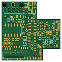
MegaAV CE VA0 is an open source PCB design by RIP-Felix, published on GitHub under the CERN-OHL-S-2.0 license. It is a 4-layer board measuring 50 × 50 mm, with 128 components from 40 distinct parts.
Other key parts include the CXA1645/CXA2075/BH7236AF, NCV8114ASN250T1G, TS924 and TS922. By type, the board carries 58 resistors, 45 capacitors, 5 ICs, 1 connector, 1 diode and 1 inductor.
It belongs with the audio and retro computing designs in this gallery.
From the project
Timeline of events: ACE9921 & Villahed94 developed the original Mega Amp 1.0. Inception for a mod board that combines the Mega Amp with an RGB video amplifier was Bob from RetroRGB's idea. Rene from db Electronics designed the first build. Tienfeng designed the second with a modi
Timeline of events: ACE9921 & Villahed94 developed the original Mega Amp 1.0. Inception for a mod board that combines the Mega Amp with an RGB video amplifier was Bob from RetroRGB's idea. Rene from db Electronics designed the first build. Tienfeng designed the second with a modified version of the then new Mega Amp 2.0, on which Jose Cruz helped with testing. That became the Triple Bypass v2.
Main components on the MegaAV CE VA0
MegaAV CE VA0 bill of materials (BOM)
128 components, 40 distinct parts — part numbers from the project's BOM.
| Qty | Part | Footprint | Refs |
|---|---|---|---|
| 1 | CXA1645/CXA2075/BH7236AF | CXA2075 | IC1 |
| 1 | NCV8114ASN250T1G | TSOT-23-5 | U2 |
| 2 | TS924 | SO-14_3.9x8.65mm_P1.27mm | U3, U7 |
| 1 | TS922 | SO-8_3.9x4.9mm_P1.27mm | U6 |
| 1 | MD-90SM_MD2 | MD90SM-MD2 | CN1 |
| 8 | ~ | SolderJumper-2_P1.3mm_Open_RoundedPad1.0x1.5mm | 32XPD1, 32XPD2, FO1, MD1_PU1, PSGPD1, PSGPD2, PSGPD3, PSGPD4 |
| 8 | SolderJumper_3_Open | SolderJumper-3_P1.3mm_Open_RoundedPad1.0x1.5mm | FML_1, FML_2, FMR_1, FMR_2, HPL_RES1, HPL_RES2, HPR_RES1, HPR_RES2 |
| 1 | Conn_01x33_Pin | Molex_502244-3330_1x33-1MP_P0.5mm_Horizontal | Z1 |
| 1 | 1N4148W | D_SOD-323 | D2 |
| 1 | 100uH | L_0805_2012Metric | L1 |
| 1 | VJ0805A330FXJPW1BC 47p | C_0402_1005Metric | C1 |
| 21 | 10uF | C_0805_2012Metric | C3, C4, C14, C15, C19, C20, C21, C22 +13 |
| 4 | 47p | C_0402_1005Metric | C9, C11, C12, C13 |
| 4 | VJ0805A330FXJPW1BC 0.1uF | C_0805_2012Metric | C32, C33, C39, C53 |
| 2 | 5.6nF | C_0402_1005Metric | C35, C36 |
| 1 | VJ0805A330FXJPW1BC 5p | C_0805_2012Metric | C38 |
| 6 | 220uF | CP_EIA-3528-15_AVX-H | C41, C45, C46, C47, C48, C56 |
| 3 | 47u | C_1206_3216Metric | C42, C43, C44 |
| 1 | 7p | C_0402_1005Metric | C49 |
| 1 | 12p | C_0402_1005Metric | C50 |
Show 20 more
| Qty | Part | Footprint | Refs |
|---|---|---|---|
| 1 | VJ0805A330FXJPW1BC 10uF | C_0805_2012Metric | C54 |
| 8 | 47k | R_0402_1005Metric | R4, R5, R7, R8, R31, R32, R59, R72 |
| 5 | 75 | R_0603_1608Metric | R15, R17, R74, R75, R76 |
| 5 | 2.2k | R_0402_1005Metric | R21, R23, R36, R67, R68 |
| 3 | 22k | R_0402_1005Metric | R22, R24, R25 |
| 2 | 36k | R_0603_1608Metric | R26, R29 |
| 4 | 51k | R_0402_1005Metric | R27, R28, R65, R79 |
| 1 | 15k | R_0402_1005Metric | R30 |
| 1 | 3.6k | R_0603_1608Metric | R33 |
| 1 | 820 | R_0603_1608Metric | R34 |
| 1 | 20k | R_0603_1608Metric | R35 |
| 3 | 5.6k | R_0603_1608Metric | R37, R38, R56 |
| 2 | 7.5k | R_0603_1608Metric | R39, R42 |
| 8 | 10k | R_0402_1005Metric | R40, R41, R46, R47, R48, R49, R62, R64 |
| 1 | 82k | R_0603_1608Metric | R45 |
| 4 | 4.7k | R_0402_1005Metric | R52, R57, R58, R66 |
| 3 | 330 | R_0402_1005Metric | R53, R54, R55 |
| 2 | 100 | R_0402_1005Metric | R60, R61 |
| 3 | 1.2k | R_0603_1608Metric | R69, R71, R73 |
| 1 | 1k | R_0402_1005Metric | R70 |
MegaAV CE VA0 design files
The KiCad project lives in the RIP-Felix/MEGA-AV-main repository on GitHub; these links point at the commit this page was built from.
MegaAV CE VA0: common questions
How big is the MegaAV CE VA0 PCB?
The MegaAV CE VA0 measures 50 × 50 mm, has 4 copper layers and is 1.6 mm thick.
How many components are on the MegaAV CE VA0?
128 components, from 40 distinct parts, with part numbers taken from the project's own BOM. The full bill of materials is listed on this page.
Where can I download the MegaAV CE VA0 design files?
From the RIP-Felix/MEGA-AV-main repository on GitHub, which has the KiCad layout, the schematic and the BOM; the links under Design files point to each one.
Can I use the MegaAV CE VA0 design in my own project?
Yes, under the terms of its CERN-OHL-S-2.0 license, which RIP-Felix chose for the repository.
More boards in MEGA-AV-main
MegaAV Pro VA0
50 × 50 mm153 parts4LCERN-OHL-S-2.047
MegaAV rev0.5
50 × 50 mm143 parts4LCERN-OHL-S-2.047
MegaAV Saturn rev0.2
40.4 × 55 mm133 parts2LCERN-OHL-S-2.047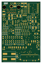
4bp ZIFF MD9
38.8 × 60.7 mm123 parts2LCERN-OHL-S-2.047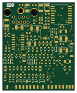
4bp NOZIFF MD9
38.8 × 47.4 mm108 parts2LCERN-OHL-S-2.047
Similar boards
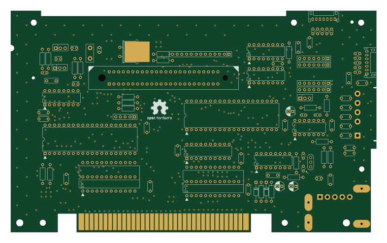
OpenTendo
Redherring32
196.3 × 118.7 mm93 parts2LTAPR-OHL-1.0850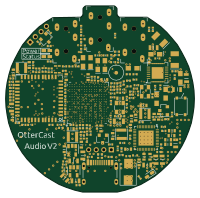
OtterCastAudioV2
Ottercast
50 × 49.3 mm216 parts4LMIT665
24pin flex interposer
Wren6991
29 × 32 mm3 parts2LNo license508
Sram dev board
50 × 50 mm12 parts2LNo license508
GB-BRK-SLOT-A
Gekkio
81 × 80 mm20 parts2LCC-BY-4.0376
GB-BRK-SLOT-B
81 × 80 mm20 parts2LCC-BY-4.0376