
2.1-sound system

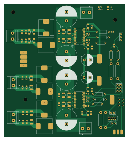
About the 2.1-sound system PCB
2.1-sound system is an open source PCB design by Royaldeadshot, published on GitHub. It is a 4-layer board measuring 102.7 × 112.3 mm, with 122 components from 37 distinct parts.
Other key parts include the TPA3255DDVR. By type, the board carries 71 capacitors, 18 resistors, 11 connectors, 10 inductors, 3 battery holders and 2 ICs.
It belongs with the audio designs in this gallery.
From the project
a 2.1 channel 900 watt sound system made by me
This project is a custom-built 3-way audio system designed from scratch, including the amplifier, crossover network, and speaker configuration. The goal was to create a solid, practical setup that delivers good sound without overcomplicating the design.
- Subwoofer: 10" DVC (handles low frequencies) - Tower Speakers (x2): - 2 × Woofers (connected in series → 8Ω) - 1 × Midrange driver (4Ω) - 1 × Tweeter (4Ω)
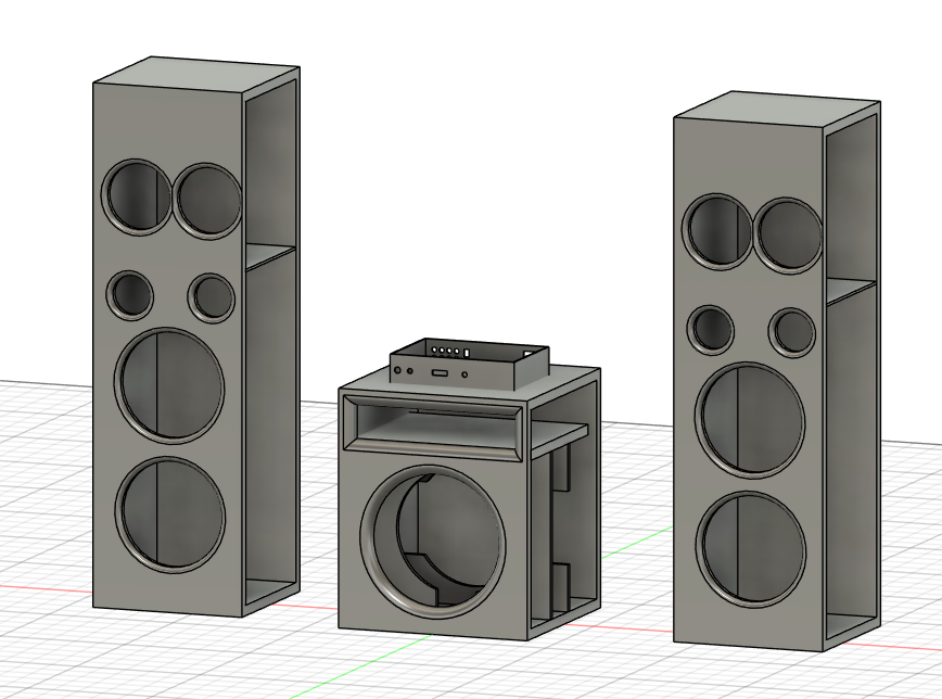
Main components on the 2.1-sound system
2.1-sound system bill of materials (BOM)
122 components, 37 distinct parts — part numbers from the project's BOM.
| Qty | Part | Footprint | Refs |
|---|---|---|---|
| 2 | TPA3255DDVR | HTSSOP-44_L14.0-W6.1-P0.64-LS8.1-BL | U1, U2 |
| 1 | +48V GND | TerminalBlock_Phoenix_MKDS-1,5-2_1x02_P5.00mm_Horizontal | J1 |
| 2 | +12V | SolderWirePad_1x01_SMD_4x8mm | J3, J13 |
| 2 | Reset Switch | PinHeader_1x02_P1.00mm_Vertical | J4, J19 |
| 2 | Fault | SolderWirePad_1x01_SMD_3x6mm | J5, J20 |
| 2 | Clip OTW | SolderWirePad_1x01_SMD_3x6mm | J6, J22 |
| 1 | +48V GND | TerminalBlock_Phoenix_MKDS-1,5-2_1x02_P5.00mm_Horizontal | J7 |
| 1 | AudioPlug4 | Plug_3.5mm_CUI_SP-3541 | J17 |
| 1 | Left | SolderWirePad_1x01_SMD_2x4mm | BT1 |
| 1 | GND | SolderWirePad_1x01_SMD_2x4mm | BT2 |
| 1 | Right | SolderWirePad_1x01_SMD_2x4mm | BT3 |
| 1 | Audio Ground | SolderWirePad_1x01_SMD_4x8mm | GND1 |
| 2 | + - | TerminalBlock_Phoenix_MKDS-1,5-2_1x02_P5.00mm_Horizontal | Left_SPK1, Right_SPK1 |
| 1 | + - | TerminalBlock_Phoenix_MKDS-1,5-2_1x02_P5.00mm_Horizontal | SUB_SPK1 |
| 1 | SW_Slide_DPDT | SW_CK_JS202011AQN_DPDT_Angled | SW1 |
| 1 | 10k Pot | Potentiometer_Alpha_RD902F-40-00D_Dual_Vertical | Volume1 |
| 1 | 10k | Potentiometer_ACP_CA6-H2,5_Horizontal | sub1 |
| 4 | 3.3 | R_1206_3216Metric_Pad1.30x1.75mm_HandSolder | FB1, FB2, FB3, FB4 |
| 6 | 10µH | L_APV_APH1265 | L1, L2, L3, L4, L5, L6 |
| 12 | 1uF | C_1210_3225Metric_Pad1.33x2.70mm_HandSolder | C1, C2, C3, C4, C26, C27, C28, C29 +4 |
Show 17 more
| Qty | Part | Footprint | Refs |
|---|---|---|---|
| 4 | 2200uF | CP_Radial_D18.0mm_P7.50mm | C5, C6, C70, C76 |
| 12 | 100nF | C_0805_2012Metric_Pad1.18x1.45mm_HandSolder | C7, C8, C9, C10, C11, C21, C40, C44 +4 |
| 2 | 470uF | CP_Radial_D10.0mm_P5.00mm | C12, C39 |
| 6 | 1uF | C_0603_1608Metric_Pad1.08x0.95mm_HandSolder | C14, C19, C20, C53, C54, C64 |
| 8 | 10uF | C_0805_2012Metric_Pad1.18x1.45mm_HandSolder | C15, C16, C17, C18, C38, C48, C49, C66 |
| 8 | 33nF | C_1206_3216Metric_Pad1.33x1.80mm_HandSolder | C22, C23, C24, C25, C41, C42, C65, C67 |
| 6 | 1nF | C_0805_2012Metric_Pad1.18x1.45mm_HandSolder | C30, C31, C32, C33, C47, C51 |
| 6 | 10nF | C_0805_2012Metric_Pad1.18x1.45mm_HandSolder | C34, C35, C36, C37, C45, C52 |
| 4 | 470nF | C_1206_3216Metric_Pad1.33x1.80mm_HandSolder | C46, C50, C55, C57 |
| 2 | 100pF | C_Disc_D5.0mm_W2.5mm_P2.50mm | C58, C59 |
| 1 | 270nF | C_0805_2012Metric_Pad1.18x1.45mm_HandSolder | C77 |
| 2 | 22k | R_Axial_DIN0207_L6.3mm_D2.5mm_P7.62mm_Horizontal | R1, R10 |
| 4 | 30k | R_Axial_DIN0207_L6.3mm_D2.5mm_P10.16mm_Horizontal | R2, R7, R11, R12 |
| 6 | 3.3 | R_1206_3216Metric_Pad1.30x1.75mm_HandSolder | R3, R4, R5, R6, R8, R9 |
| 2 | 470ohm | R_Axial_DIN0411_L9.9mm_D3.6mm_P12.70mm_Horizontal | R13, R14 |
| 2 | 4.7k | R_Axial_DIN0411_L9.9mm_D3.6mm_P12.70mm_Horizontal | R15, R16 |
| 2 | 10k | R_Axial_DIN0207_L6.3mm_D2.5mm_P7.62mm_Horizontal | R17, R18 |
2.1-sound system design files
The KiCad project lives in the Royaldeadshot/2.1-sound-system repository on GitHub; these links point at the commit this page was built from.
- LayoutPCB/amplifier.kicad_pcb
- SchematicPCB/amplifier.kicad_sch
- BOMbom.csv
2.1-sound system: common questions
How big is the 2.1-sound system PCB?
The 2.1-sound system measures 102.7 × 112.3 mm, has 4 copper layers and is 1.6 mm thick.
How many components are on the 2.1-sound system?
122 components, from 37 distinct parts, with part numbers taken from the project's own BOM. The full bill of materials is listed on this page.
Where can I download the 2.1-sound system design files?
From the Royaldeadshot/2.1-sound-system repository on GitHub, which has the KiCad layout, the schematic and the BOM; the links under Design files point to each one.
Can I use the 2.1-sound system design in my own project?
The repository has no license, so all rights stay with Royaldeadshot. Use it as a reference, and ask the author before reusing the design.
Similar boards
KLOR
GEIGEIGEIST
160.2 × 118.3 mm79 parts2LGPL-3.01.2k
ButtonsLEDs
shanteacontrols
390 × 37 mm82 parts2LApache-2.0956
USB
52 × 12.6 mm6 parts2LApache-2.0956
Pots
390 × 93 mm75 parts2LApache-2.0956
PicoGUS Hand386
polpo
29.2 × 75.2 mm43 parts4LGPL-2.0800
Snark barker
schlae
231.1 × 106.7 mm193 parts2LNo license687