
Ruuvitracker hw

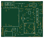
About the Ruuvitracker hw PCB
Ruuvitracker hw is an open source STM32 PCB design by ruuvi, published on GitHub. It is a board measuring 38.9 × 33.4 mm, with 135 components from 47 distinct parts.
Its main chip is the STM32F10XXX_LQFP64, from the STM32 family. Other key parts include the SIM968, MMA8652FC, TPS783XX, TPD2S017 and MCP73831. By type, the board carries 58 connectors, 32 capacitors, 22 resistors, 10 ICs, 4 diodes and 2 switches.
From the project
Latest hardware version is Rev.C3. First one was Rev.A1 and then Rev.B1 came out. And after that, Rev.C1 and Rev.C2. Revisions A, B and C are completely different devices.
Latest hardware version is Rev.C3. First one was Rev.A1 and then Rev.B1 came out. And after that, Rev.C1 and Rev.C2. Revisions A, B and C are completely different devices.
All the design files are licensed under Attribution-ShareAlike 4.0 International (CC BY-SA 4.0). Copyright Lauri Jämsä, Ruuvi Innovations Ltd. Neither the name of the RuuviTracker nor the names of its contributors may be used to endorse or promote products derived from this project without specific prior written permission. While unofficial products should not have "Ruuvi" in their name, it's okay to describe your product…
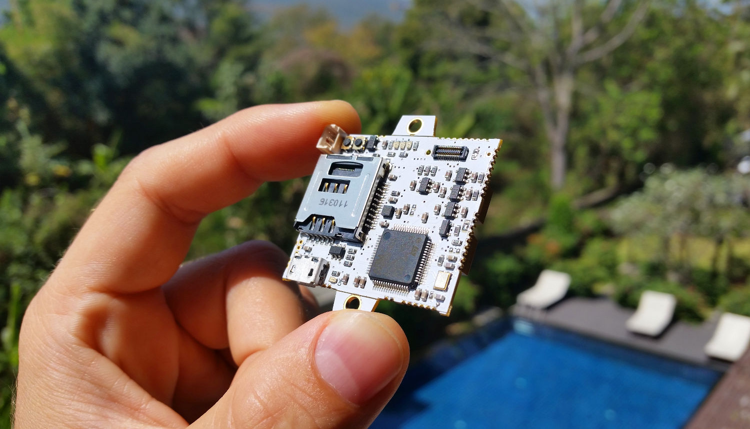
Main components on the Ruuvitracker hw
Ruuvitracker hw bill of materials (BOM)
135 components, 47 distinct parts — part numbers from the project's BOM.
| Qty | Part | Footprint | Refs |
|---|---|---|---|
| 1 | STM32F10XXX_LQFP64 | LQFP-64 | U1 |
| 1 | SIM968 | SIM968_RECT | U2 |
| 1 | MMA8652FC | DFN_10PIN_2X2MM | U3 |
| 4 | TPS783XX | SOT23-5 | U4, U5, U6, U11 |
| 1 | TPD2S017 | SOT23-6 | U7 |
| 1 | MCP73831 | SOT23-5 | U8 |
| 1 | MICROSD_SIM_COMBO | COMBO_CARDSLOT_MES3051_OPTIMIZED | U9 |
| 1 | MOSFET_P | SOT23-GDS | Q1 |
| 1 | 8-24MHZ | ABM8G_3_2X2_5MM_4PIN_CRYSTAL | X1 |
| 1 | USB_MICRO_B | MICROUSB_B_10118192-0001LF | J1 |
| 1 | IPROTOXI_CONN | DF37NB-24DS-04V | P1 |
| 1 | GPS_CONN | UFL-R-SMT | P2 |
| 1 | GSM_CONN | UFL-R-SMT | P3 |
| 4 | FIDU | TP_SMD_08MM | P4, P9, P10, P11 |
| 1 | GSM_SPK | 005INCH_PINSTRIP_THRUHOLE_2PIN | P5 |
| 1 | GSM_MIC | 005INCH_PINSTRIP_THRUHOLE_2PIN | P6 |
| 1 | GSM_ANT | 005INCH_PINSTRIP_THRUHOLE_1PIN | P7 |
| 1 | ALIGNMENT | 1MM_THRUHOLE_1PIN | P8 |
| 1 | 5V_IN | 005INCH_PINSTRIP_THRUHOLE_2PIN | P12 |
| 43 | CONN_1 | 005INCH_PINSTRIP_THRUHOLE_1PIN | P13, P14, P15, P16, P17, P18, P19, P20 +35 |
Show 27 more
| Qty | Part | Footprint | Refs |
|---|---|---|---|
| 2 | HOLE | 3MM_PLATED_HOLE | P48, P49 |
| 1 | BATTERY | 53047-0310_3PIN_THRU | K1 |
| 2 | SOLDER_JUMPER_3_PASTE1&2 | SOLDER_JUMPER_3_PASTE12 | SJ1, SJ3 |
| 2 | SOLDER_JUMPER_2_PASTE1&2 | SOLDER_JUMPER_2_PASTE12 | SJ2, SJ4 |
| 1 | WKUP_BUT | SKSGPAE010 | SW1 |
| 1 | BOOT0_BUT | SKSGPAE010 | SW2 |
| 1 | LED_RED | LED_SMD-0603 | D1 |
| 2 | LED_GREEN | LED_SMD-0603 | D2, D3 |
| 1 | LED_CHG | LED_SMD-0603 | D4 |
| 6 | 220n | SMD_0603_RT | C1, C2, C3, C4, C5, C7 |
| 17 | 2u2 | SMD_0603_RT | C6, C8, C9, C10, C11, C12, C13, C14 +9 |
| 2 | 680u | TANTALUM_D_E_2917 | C18, C19 |
| 1 | GPSCAP1 | SMD_0603_RT | C20 |
| 1 | GSMCAP1 | SMD_0603_RT | C21 |
| 1 | GPSCAP2 | SMD_0603_RT | C22 |
| 1 | GSMCAP2 | SMD_0603_RT | C23 |
| 2 | 10p | SMD_0603_RT | C24, C26 |
| 1 | NA | SMD_0603_RT | C32 |
| 5 | 47k | SMD_0603_RT | R1, R2, R3, R4, R13 |
| 3 | 10 | SMD_0603_RT | R5, R6, R17 |
| 2 | 2k | SMD_0603_RT | R7, R22 |
| 4 | 330 | SMD_0603_RT | R8, R9, R10, R21 |
| 4 | 4k7 | SMD_0603_RT | R11, R12, R23, R24 |
| 1 | NA | SMD_0603_RT | R14 |
| 1 | GPSRES | SMD_0603_RT | R18 |
| 1 | GSMRES1 | SMD_0603_RT | R19 |
| 1 | GSMRES2 | SMD_0603_RT | R20 |
Ruuvitracker hw design files
The KiCad project lives in the ruuvi/ruuvitracker_hw repository on GitHub; these links point at the commit this page was built from.
Ruuvitracker hw: common questions
What microcontroller does the Ruuvitracker hw use?
The Ruuvitracker hw is built around the STM32F10XXX_LQFP64, from the STM32 family.
How big is the Ruuvitracker hw PCB?
The Ruuvitracker hw measures 38.9 × 33.4 mm and is 1.6 mm thick.
How many components are on the Ruuvitracker hw?
135 components, from 47 distinct parts, with part numbers taken from the project's own BOM. The full bill of materials is listed on this page.
Where can I download the Ruuvitracker hw design files?
From the ruuvi/ruuvitracker_hw repository on GitHub, which has the KiCad layout and the BOM; the links under Design files point to each one.
Can I use the Ruuvitracker hw design in my own project?
The repository has no license, so all rights stay with ruuvi. Use it as a reference, and ask the author before reusing the design.
Can I test firmware for the Ruuvitracker hw without the hardware?
Yes. HardLabs builds a simulation of the board from its netlist and BOM, so you can run and debug STM32 firmware against it before you order a PCB.
Similar boards
 STM32
STM32LumenPnP Motherboard
opulo-inc
149 × 95 mm296 parts4LCC-BY-SA-4.03.7k STM32
STM32AxxSolder
AxxAxx
39 × 82.5 mm122 parts2LGPL-3.01.7k STM32
STM32AIOC
skuep
21 × 31.5 mm47 parts2LMIT1.4k STM32
STM32Ferris
pierrechevalier83
208.8 × 86.8 mm102 parts2LSHL-2.11.3k STM32
STM32Module 16S
stuartpittaway
71.1 × 89.6 mm113 parts4LCC-BY-NC-4.01.1k STM32
STM32Djinn
tzarc
192.3 × 150.5 mm216 parts2LCERN-OHL-S-2.0988