
10 open source boards using the TPD2S017
Real designs built with the TPD2S017, from public GitHub projects: a quick way to see how others power, decouple and connect it. Each board comes with its KiCad files, full parts list and a render — and you can simulate its firmware on HardLabs.
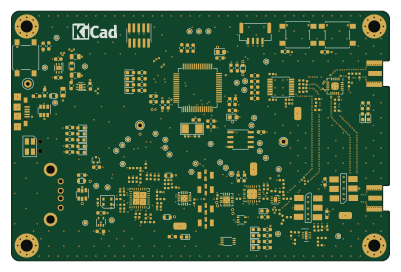 STM32
VNA
joshajohnson
100 × 66 mm207 parts2LGPL-3.025 STM32
Ruuvitracker hw
ruuvi
38.9 × 33.4 mm135 partsNo license14 Nordic nRF
Mk2
jeffc
23.5 × 37.5 mm49 parts2LNo license6 STM32
Ruuvilogger hw
38 × 15 mm93 partsNo license5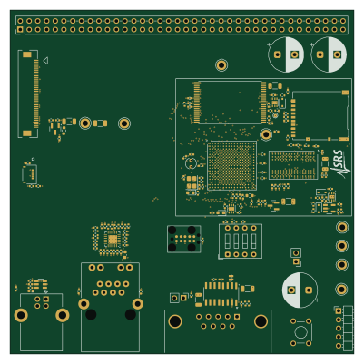 STM32
Stm32mp135 test board
js216
100 × 100 mm193 parts6LNo license4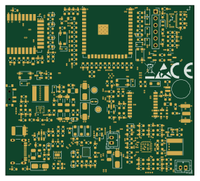 ESP32
UWB Module ESP IDF
victorstoica114
71 × 64 mm248 parts4LNo license1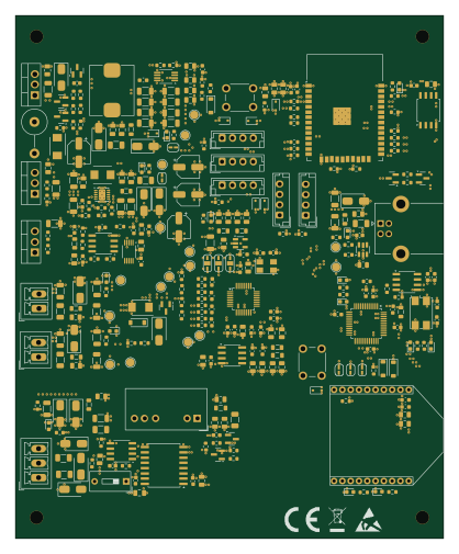 ESP32
Senzori iradiere
cs-pub-ro
103 × 126 mm328 parts4LNo license0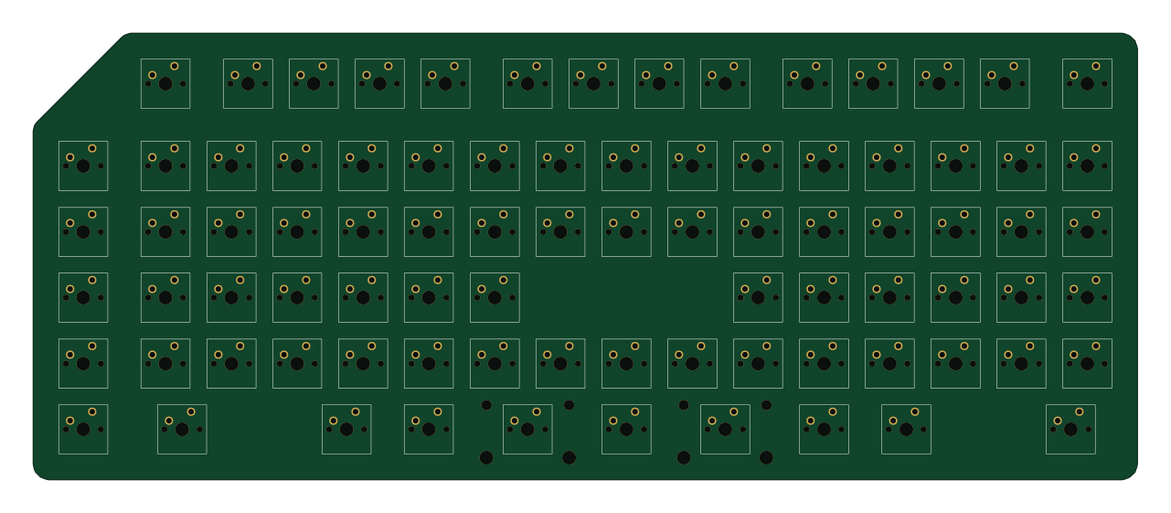 AVR/Arduino
Ortho Allison
kajahtaa
319.7 × 129.2 mm186 parts2LNo license0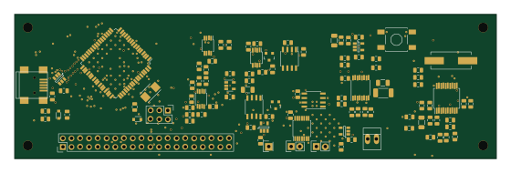 AVR/Arduino
GlazerLab KStat
nfroehberg
139.7 × 41.9 mm116 parts2LNo license0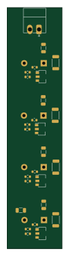
Supercapacitors balancing
21 × 92 mm30 parts2LNo license0
How designs wire the TPD2S017
Read from the KiCad layouts of 9 open source designs, one per repository: what each pin of the TPD2S017 connects to, and the resistors, capacitors and other passives placed on it.
- The CH1OUT pin has a series resistor on 6 of 9 designs, most often 0 Ω (then 10 Ω).
- The CH2OUT pin has a series resistor on 6 of 9 designs, most often 0 Ω (then 10 Ω).
- The VCC pin has a decoupling capacitor on 4 of 9 designs, most often 100 nF (then 10 µF).
| Pin | Connected to | Parts on the pin |
|---|---|---|
| CH1OUTpin 1 | Connected to: The microcontroller 22% |
|
| GNDpin 2 | Connected to: GND 89% | — |
| VCCpin 5 | Connected to: 5V 78% · a signal 22% |
|
| CH2OUTpin 6 | Connected to: The microcontroller 22% |
|
2 more pins vary from design to design. Connections count pins, parts count designs; values in brackets are how many parts had that value. Designs read include VNA by joshajohnson, Ruuvitracker hw by ruuvi, Mk2 by jeffc and Ruuvilogger hw by ruuvi.
The TPD2S017 in open source designs
The gallery holds 10 open source boards using the TPD2S017 from 9 GitHub repositories; a typical one measures about 85.5 × 65 mm and carries around 161 components.
63% are two-layer designs, the rest use four layers or more, and 10% carry an open source license.
The most starred is VNA by joshajohnson.
Parts used alongside the TPD2S017
Microcontrollers on boards using the TPD2S017
What boards using the TPD2S017 are built for
TPD2S017: common questions
Where can I find a TPD2S017 reference design?
Each of the 10 boards on this page is a real design using the TPD2S017. Open one to see how it is wired up, with the full BOM, a render of the layout and links to its KiCad files.
What resistor goes on the TPD2S017 CH1OUT pin?
The CH1OUT pin has a series resistor on 6 of 9 designs, most often 0 Ω (then 10 Ω). Counted from the KiCad layouts of 9 open source designs using the TPD2S017.
What resistor goes on the TPD2S017 CH2OUT pin?
The CH2OUT pin has a series resistor on 6 of 9 designs, most often 0 Ω (then 10 Ω). Counted from the KiCad layouts of 9 open source designs using the TPD2S017.
What decoupling capacitors do designs use on the TPD2S017 VCC pin?
The VCC pin has a decoupling capacitor on 4 of 9 designs, most often 100 nF (then 10 µF). Counted from the KiCad layouts of 9 open source designs using the TPD2S017.
What parts are used alongside the TPD2S017?
The MCP73831, MMA8652FC and TPS783XX appear in the most repositories here.
Which microcontrollers do boards using the TPD2S017 use?
Most are built on STM32 (4), AVR/Arduino (2), ESP32 (2) and Nordic nRF (1).
How big is a typical board using the TPD2S017?
The median is 85.5 × 65 mm, and 63% are two-layer designs.
What is the most popular open source board using the TPD2S017?
By GitHub stars, VNA by joshajohnson, with 25 stars.
Can I simulate one of these boards using the TPD2S017 before building it?
Yes. HardLabs turns a board's netlist and BOM into a working simulation, so you can boot and test firmware against it with no hardware on your desk.