
SolarOptimizer

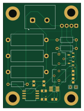
About the SolarOptimizer PCB
SolarOptimizer is an open source PCB design by RyanMarienthal, published on GitHub. It is a 2-layer board measuring 41 × 55.5 mm, with 23 components from 18 distinct parts.
Other key parts include the TLV1805DBVR and LM317LCDR. By type, the board carries 11 resistors, 4 connectors, 2 ICs, 2 transistors and 2 capacitors.
It belongs with the power & battery designs in this gallery.
From the project
This project contains KiCad files for a solar power optimizer circuit which replaces an MPPT controller and increases power and holds system voltage constant.
This project contains the design of a solar power optimizer.
The project was designed in KiCad, and the files are provided and can be edited to the users demands.
The project has generic values for R1, R2, R3, and R4 because they are intended to be chosen by the user depending on the voltage of the system.
Standard divider sizes are shown below: 48V OCV: R1 = 40kOhm, R2 = 7500Ohm, R3 = 1000Ohm, R4 = 2000Ohm R1 and R2 must be rated for at least 1/8 Watt. R3 and R4 must be rated for at least 1 Watt.
Main components on the SolarOptimizer
SolarOptimizer bill of materials (BOM)
23 components, 18 distinct parts.
| Qty | Part | Footprint | Refs |
|---|---|---|---|
| 1 | TLV1805DBVR | TSOT-23-6_HandSoldering | U1 |
| 1 | LM317LCDR | SOIC-8_5.3x6.2mm_P1.27mm | U2 |
| 1 | N-Channel | SOT-23-3 | Q1_N |
| 1 | P-Channel | SOT-23-3 | Q2_P |
| 2 | ~ | Pin_D0.7mm_L6.5mm_W1.8mm_FlatFork | J1, J3 |
| 1 | Screw_Terminal_01x02 | TerminalBlock_gauge 10 | J2 |
| 1 | Screw_Terminal_01x04 | 4Pin_Terminal_NoSilk | J5 |
| 1 | 20 kOhm | TRIM_3362P-1-253LF | Rp1 |
| 1 | 100 kOhm | TRIM_3362P-1-253LF | Rp3 |
| 1 | 0.1 uF | C_0805_2012Metric_Pad1.18x1.45mm_HandSolder | C1 |
| 1 | 1 uF | C_0805_2012Metric_Pad1.18x1.45mm_HandSolder | C2 |
| 3 | R | R_Axial_DIN0207_L6.3mm_D2.5mm_P10.16mm_Horizontal | R1, R2, R4 |
| 1 | 4k7 | R_0805_2012Metric_Pad1.20x1.40mm_HandSolder | R3_4k7 |
| 3 | R | R_Axial_DIN0617_L17.0mm_D6.0mm_P20.32mm_Horizontal | R3_P1, R3_P2, R3_P3 |
| 1 | 470 | R_0805_2012Metric_Pad1.20x1.40mm_HandSolder | R5_470 |
| 1 | 330 | R_0805_2012Metric_Pad1.20x1.40mm_HandSolder | R7 |
| 1 | 10k | R_0805_2012Metric_Pad1.20x1.40mm_HandSolder | R10 |
| 1 | 1 MOhm | R_0805_2012Metric_Pad1.20x1.40mm_HandSolder | R61M |
SolarOptimizer design files
The KiCad project lives in the RyanMarienthal/SolarOptimizer repository on GitHub; these links point at the commit this page was built from.
SolarOptimizer: common questions
How big is the SolarOptimizer PCB?
The SolarOptimizer measures 41 × 55.5 mm, has 2 copper layers and is 1.6 mm thick.
How many components are on the SolarOptimizer?
23 components, from 18 distinct parts. The full bill of materials is listed on this page.
Where can I download the SolarOptimizer design files?
From the RyanMarienthal/SolarOptimizer repository on GitHub, which has the KiCad layout and the schematic; the links under Design files point to each one.
Can I use the SolarOptimizer design in my own project?
The repository has no license, so all rights stay with RyanMarienthal. Use it as a reference, and ask the author before reusing the design.
Similar boards

EinkPDA screen
TalismanDesign
95 × 54 mm27 parts2LApache-2.02.0k
Stack chan
stack-chan
50 × 50 mm33 parts2LApache-2.01.7k
Display Carrier
AxxAxx
35.6 × 58.2 mm5 parts2LGPL-3.01.7k
ProgrammingAdapter
stuartpittaway
10.5 × 83 mm3 parts2LCC-BY-NC-4.01.1k
TemperaturePCB PANEL
116 × 75.5 mm178 parts2LCC-BY-NC-4.01.1k
Module 16S PassiveBalanceAddOn
61 × 74 mm86 parts2LCC-BY-NC-4.01.1k