
Picolino-CPC

About the Picolino-CPC PCB
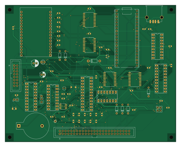
Picolino-CPC is an open source RP2040/RP2350 PCB design by salvogendut, published on GitHub under the GPL-3.0 license. It is a 2-layer board measuring 150 × 120 mm, with 81 components from 37 distinct parts.
Its main chip is the Raspberry Pi Pico 2, from the RP2040/RP2350 family. Other key parts include the GAL20V8B / picolino.jed, 74HCT21, SN74CB3T3245DW, W5100S reference module and PIC16F84A / Cyboard HEX. By type, the board carries 31 resistors, 17 capacitors, 13 ICs, 8 diodes, 4 connectors and 2 jumpers.
From the project
A PICO-based expansion board for the CPC
The editable KiCad 10 project contains a cover sheet and four circuit sheets: bus/power, Pico ROM interface, Ethernet/mouse and RTC. The PCB is 150 × 120 mm, two copper layers, 1.6 mm nominal thickness, with four 3.2 mm non-plated mounting holes on a 142 × 112 mm rectangle. Nominal signal tracks are 0.25 mm; power distribution is 0.80 mm, with pad escapes where needed. The project minimum is 0.20 mm track/clearance and 0.30 mm drilled vias; routed vias use 0.70/0.35 mm diameter/drill. Ground pours occupy both layers.
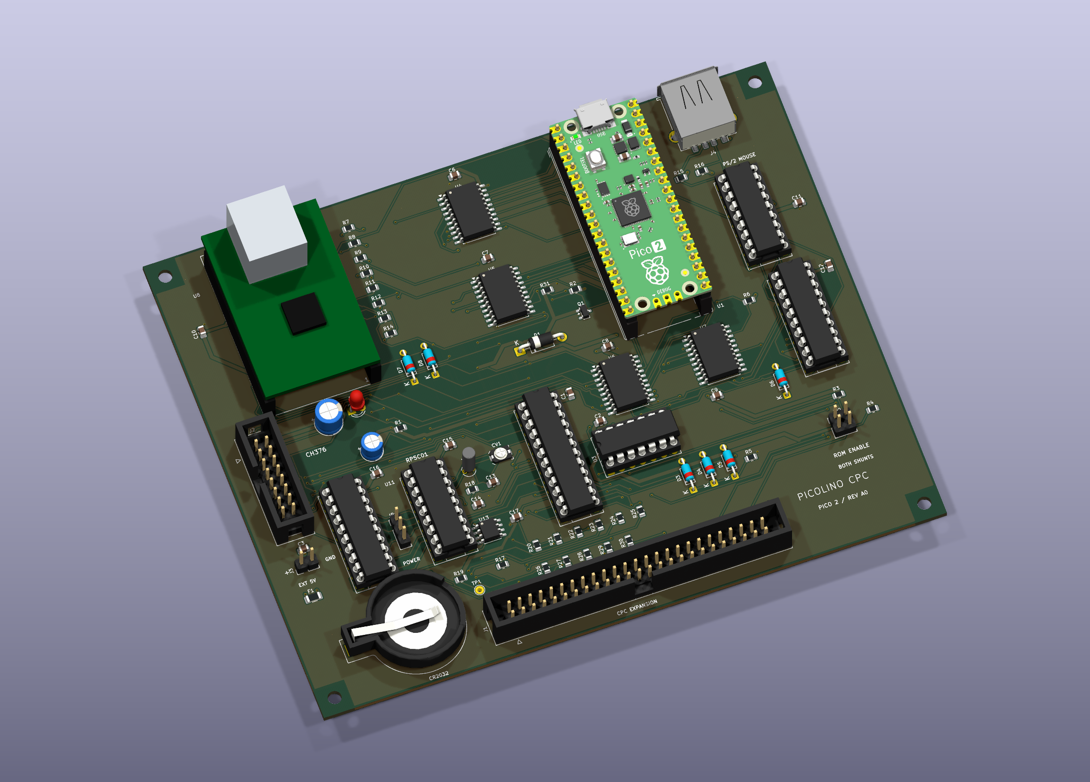
Main components on the Picolino-CPC
Picolino-CPC bill of materials (BOM)
81 components, 37 distinct parts — part numbers from the project's BOM.
| Qty | Part | Footprint | Refs |
|---|---|---|---|
| 1 | Raspberry Pi Pico 2 | Pico2_Socketed | U1 |
| 1 | GAL20V8B / picolino.jed | DIP-24_W7.62mm_Socket_LongPads | U2 |
| 1 | 74HCT21 | DIP-14_W7.62mm_Socket_LongPads | U3 |
| 4 | SN74CB3T3245DW | SOIC-20W_7.5x12.8mm_P1.27mm | U4, U5, U6, U7 |
| 1 | W5100S reference module | W5100S_Cyboard | U8 |
| 1 | PIC16F84A / Cyboard HEX | DIP-18_W7.62mm_Socket_LongPads | U9 |
| 1 | 74HCT244 | DIP-20_W7.62mm_Socket_LongPads | U10 |
| 1 | RP5C01 (original, DIP-18) | DIP-18_W7.62mm_Socket_LongPads | U11 |
| 1 | 74HCT373 | DIP-20_W7.62mm_Socket_LongPads | U12 |
| 1 | MAX690AESA+ | SOIC-8_3.9x4.9mm_P1.27mm | U13 |
| 1 | 2N7002 | SOT-23 | Q1 |
| 1 | 32.768kHz / AB38T | Crystal_C38-LF_D3.0mm_L8.0mm_Vertical | Y1 |
| 1 | CPC 50-pin expansion | IDC-Header_2x25_P2.54mm_Vertical | J1 |
| 1 | CH376 parallel / short ribbon | IDC-Header_2x08_P2.54mm_Vertical | J2 |
| 1 | EXT regulated 5V | PinHeader_1x02_P2.54mm_Vertical | J3 |
| 1 | PS/2 MOUSE only | USB_A_TE_292303-7_Horizontal | J4 |
| 1 | CR2032 / Keystone 103 | BatteryHolder_Keystone_103_1x20mm | BT1 |
| 1 | 30pF trim / KKT330TR | C_Trimmer_Murata_TZC3 | CV1 |
| 1 | USB 500mA hold | Fuse_1206_3216Metric | F1 |
| 1 | POWER: 1 CPC / 2 BOARD / 3 EXT | PinHeader_1x03_P2.54mm_Vertical | JP1 |
Show 17 more
| Qty | Part | Footprint | Refs |
|---|---|---|---|
| 1 | ROM ENABLE: fit BOTH shunts | PinHeader_2x02_P2.54mm_Vertical | JP2 |
| 1 | RTC ALARM / calibration | TestPoint_THTPad_D2.0mm_Drill1.0mm | TP1 |
| 1 | 1N5817 | D_DO-41_SOD81_P10.16mm_Horizontal | D1 |
| 1 | USB activity | LED_D3.0mm | D2 |
| 4 | BAT43 | D_DO-35_SOD27_P7.62mm_Horizontal | D3, D4, D5, D6 |
| 2 | 1N4148 | D_DO-35_SOD27_P7.62mm_Horizontal | D7, D8 |
| 13 | 100NF 100nF | C_0805_2012Metric | C1, C2, C3, C6, C7, C8, C9, C10 +5 |
| 1 | 100uF / 10V | CP_Radial_D6.3mm_P2.50mm | C4 |
| 1 | 47uF / 10V | CP_Radial_D5.0mm_P2.00mm | C5 |
| 1 | 30pF C0G | C_0805_2012Metric | C13 |
| 1 | 56pF C0G | C_0805_2012Metric | C14 |
| 1 | 1k | R_0805_2012Metric | R1 |
| 7 | 10K 10k | R_0805_2012Metric | R2, R3, R4, R6, R15, R16, R19 |
| 1 | 2.2K 2.2k | R_0805_2012Metric | R5 |
| 8 | 470 | R_0805_2012Metric | R7, R8, R9, R10, R11, R12, R13, R14 |
| 3 | 100K 100k | R_0805_2012Metric | R17, R18, R31 |
| 11 | 220K 220k | R_0805_2012Metric | R20, R21, R22, R23, R24, R25, R26, R27 +3 |
Picolino-CPC design files
The KiCad project lives in the salvogendut/picolino-CPC repository on GitHub; these links point at the commit this page was built from.
Picolino-CPC: common questions
What microcontroller does the Picolino-CPC use?
The Picolino-CPC is built around the Raspberry Pi Pico 2, from the RP2040/RP2350 family.
How big is the Picolino-CPC PCB?
The Picolino-CPC measures 150 × 120 mm, has 2 copper layers and is 1.6 mm thick.
How many components are on the Picolino-CPC?
81 components, from 37 distinct parts, with part numbers taken from the project's own BOM. The full bill of materials is listed on this page.
Where can I download the Picolino-CPC design files?
From the salvogendut/picolino-CPC repository on GitHub, which has the KiCad layout, the schematic and the BOM; the links under Design files point to each one.
Can I use the Picolino-CPC design in my own project?
Yes, under the terms of its GPL-3.0 license, which salvogendut chose for the repository.
Can I test firmware for the Picolino-CPC without the hardware?
Yes. HardLabs builds a simulation of the board from its netlist and BOM, so you can run and debug RP2040/RP2350 firmware against it before you order a PCB.
Similar boards
 RP2040/RP2350
Open Book Abridged Edition
joeycastillo
85 × 115 mm29 parts2LCC-BY-SA-4.08.1k RP2040/RP2350
Corne
foostan
277.2 × 107.5 mm164 parts2LCC-BY-4.07.7k RP2040/RP2350
Corne
277.2 × 107.5 mm164 parts2LCC-BY-4.07.7k RP2040/RP2350
LogicAnalyzer
gusmanb
57 × 55.2 mm6 parts2LGPL-3.05.0k RP2040/RP2350
Jitx design
55.5 × 65 mm26 parts4LGPL-3.05.0k RP2040/RP2350
Main
google
98 × 71 mm102 parts2LApache-2.02.9k