
Attenuverter

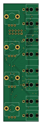
About the Attenuverter PCB
Attenuverter is an open source PCB design by schenkzoola, published on GitHub under the CC-BY-NC-4.0 license. It is a 2-layer board measuring 30 × 100 mm, with 66 components from 15 distinct parts.
Other key parts include the TL074CDR and LM4040DYM3-5.0. By type, the board carries 29 resistors, 11 diodes, 9 connectors, 9 capacitors, 2 ICs and 2 fuses.
It belongs with the audio designs in this gallery.
From the project
A 4 channel eurorack attenuverter
A 6HP Eurorack quad attenuverter from Schenktronics. Each of its four channels scales a signal by anywhere from ×1, through zero, to ×−1 (inverted), with a click at zero. Every input is normalled to +5 V, so with nothing plugged in, each channel is a manual offset from −5 V to +5 V.
- 6HP Eurorack, 20 mm deep. 16 mA on +12 V and 9 mA on −12 V. - Four channels, each turning a signal down, off, or upside down - Center-detent knobs, so zero is easy to find by feel - Inputs normalled to +5 V: four manual offset voltages when nothing's plugged in - Reverse-power protection on both rails

Main components on the Attenuverter
Attenuverter bill of materials (BOM)
66 components, 15 distinct parts — part numbers from the project's BOM.
| Qty | Part | Footprint | Refs |
|---|---|---|---|
| 1 | TL074CDR TL074 Texas Instruments | SOIC-14_3.9x8.7mm_P1.27mm | U1 |
| 1 | LM4040DYM3-5.0 LM4040DIM3X-5.0/NOPB Microchip Technology | SOT-23 | U2 |
| 8 | MJ-3507 AudioJack2_SwitchT CUI Devices | Jack_3.5mm_QingPu_WQP-PJ398SM_Vertical_CenterHole_OvalPads | J1, J2, J3, J4, J5, J6, J8, J9 |
| 1 | 302-S101 Conn_02x05_Odd_Even On Shore Technology Inc. | PinHeader_2x05_P2.54mm_Vertical_Shrouded | J7 |
| 2 | 0ZCJ0020FF2E Polyfuse Bel Fuse Inc. | Fuse_1206_3216Metric | F1, F2 |
| 4 | PTV09A-4225F-B104 100k Bourns Inc. | Potentiometer_Alps_RK09L_Plated_Mount_Holes | RV1, RV2, RV3, RV4 |
| 2 | MRA4003T3G D ON Semiconductor | D_SMA | D1, D2 |
| 9 | D | D_SOD-323 | D3, D4, D5, D6, D7, D8, D9, D10 +1 |
| 4 | CC0805JRNPO9BN100 10pF Yageo | C_0805_2012Metric | C1, C2, C3, C7 |
| 3 | 08053C104KAT2A 100nF AVX Corporation | C_0805_2012Metric | C4, C6, C9 |
| 2 | TMK212BBJ106KG-T 10uF Taiyo Yuden | C_0805_2012Metric | C5, C8 |
| 16 | RC0805FR-07100KL 100k Yageo | R_0805_2012Metric | R1, R2, R4, R5, R6, R7, R9, R10 +8 |
| 4 | RC0805FR-07100RL 1k Yageo | R_0805_2012Metric | R3, R8, R14, R19 |
| 1 | RC0805FR-071KL 1k Yageo | R_0805_2012Metric | R11 |
| 8 | 1k | R_0805_2012Metric | R22, R23, R24, R25, R26, R27, R28, R29 |
Attenuverter design files
The KiCad project lives in the schenkzoola/ST03-attenuverter repository on GitHub; these links point at the commit this page was built from.
Attenuverter: common questions
How big is the Attenuverter PCB?
The Attenuverter measures 30 × 100 mm, has 2 copper layers and is 1.6 mm thick.
How many components are on the Attenuverter?
66 components, from 15 distinct parts, with part numbers taken from the project's own BOM. The full bill of materials is listed on this page.
Where can I download the Attenuverter design files?
From the schenkzoola/ST03-attenuverter repository on GitHub, which has the KiCad layout, the schematic and the BOM; the links under Design files point to each one.
Can I use the Attenuverter design in my own project?
It is published under CC-BY-NC-4.0, which limits how it may be reused; read the license before building on it.
Similar boards
KLOR
GEIGEIGEIST
160.2 × 118.3 mm79 parts2LGPL-3.01.2k
USB
shanteacontrols
52 × 12.6 mm6 parts2LApache-2.0956
Pots
390 × 93 mm75 parts2LApache-2.0956
ButtonsLEDs
390 × 37 mm82 parts2LApache-2.0956
PicoGUS Hand386
polpo
29.2 × 75.2 mm43 parts4LGPL-2.0800
Snark barker
schlae
231.1 × 106.7 mm193 parts2LNo license687