
The Spankulator

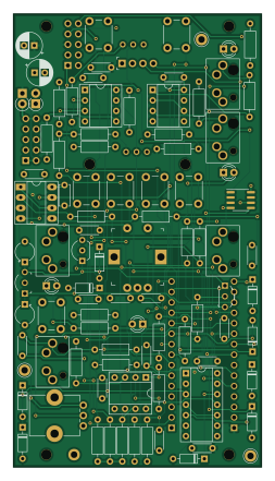
About the The Spankulator PCB
The Spankulator is an open source AVR/Arduino PCB design by shannon-greenlight, published on GitHub. It is a 4-layer board measuring 60.4 × 110 mm, with 100 components from 43 distinct parts.
Its main chip is the Arduino Socket, from the AVR/Arduino family. Other key parts include the TL072CP, CD4013BE, MC78L05_TO92, LP2950-3.3_TO92 and MAX7480. By type, the board carries 30 resistors, 21 capacitors, 15 diodes, 10 connectors, 8 ICs and 8 switches.
It belongs with the audio and iot & wireless designs in this gallery.
From the project
The Spankulator is a WiFi-enabled multi-function Eurorack module. Its main function is to generate a trio of coordinated analog and digital signals which can be used in an endless variety of ways. While each output generates familiar signals, it is the coordination of these signa
The Spankulator is a WiFi-enabled multi-function Eurorack module. Its main function is to generate a trio of coordinated analog and digital signals which can be used in an endless variety of ways. While each output generates familiar signals, it is the coordination of these signals and the methods of control that make the Spankulator special.
If starting from a bare circuit board, the BOM for the Spankulator is in bom/Digi-Key/spankulator_full.csv. This file can be directly uploaded to Digi-Key for buying parts.
Main components on the The Spankulator
The Spankulator bill of materials (BOM)
100 components, 43 distinct parts — part numbers from the project's BOM.
| Qty | Part | Footprint | Refs |
|---|---|---|---|
| 2 | TL072CP | DIP-8_W7.62mm_Socket | U1, U3 |
| 1 | CD4013BE | DIP-14_W7.62mm_Socket | U2 |
| 1 | MC78L05_TO92 | TO-92_Inline_Wide | U4 |
| 1 | LP2950-3.3_TO92 | TO-92-3_Formed_Leads | U5 |
| 1 | MAX7480 | DIP-8_W7.62mm_Socket_LongPads | U6 |
| 1 | MB85RC256 | SOIC-8_3.9x4.9mm_P1.27mm | U7 |
| 1 | MCP6002-E/P | DIP-8_W7.62mm_Socket | U8 |
| 1 | 2N3904 | TO-92-3_Formed_Leads | Q1 |
| 5 | 3.5mm Jack | Molex-0472570001 | J1, J3, J4, J5, J6 |
| 2 | 2x5 Header | PinHeader_2x05_P2.54mm_Vertical | J2, J7 |
| 1 | 0022232041 Display Header Molex | OLED_Header_Slim | J9 |
| 2 | Arduino Socket | ArduinoConnector | J12, J13 |
| 1 | 1K | Potentiometer_Bourns_PTV09A-1_Single_Vertical | RV1 |
| 1 | 20K | Potentiometer_Bourns_3266Y_Vertical | RV2 |
| 1 | 20K | Potentiometer_Bourns_3266Y_Vertical | RV3 |
| 1 | Adj | Rotary_Encoder_Switched_PEC11R | SW1 |
| 7 | Push Button | SW_PUSH_6mm | SW2, SW3, SW4, SW5, SW6, SW7, SW8 |
| 4 | TestPoint | TestPoint_Keystone_5005-5009_Compact | TP1, TP2, TP3, TP4 |
| 7 | 1N5711 | D_DO-35_SOD27_P7.62mm_Horizontal | D1, D2, D7, D15, D16, D19, D20 |
| 1 | GREEN LED | LED_D3.0mm | D3 |
Show 23 more
| Qty | Part | Footprint | Refs |
|---|---|---|---|
| 1 | BLUE LED | LED_D3.0mm | D4 |
| 1 | YELLOW LED | LED_D3.0mm | D5 |
| 2 | 1N4148 | D_DO-35_SOD27_P7.62mm_Horizontal | D6, D13 |
| 1 | 1N5819 | D_DO-41_SOD81_P2.54mm_Vertical_AnodeUp | D8 |
| 1 | 1N5819 | D_DO-41_SOD81_P2.54mm_Vertical_KathodeUp | D9 |
| 1 | RED LED | LED_D3.0mm | D14 |
| 4 | 10nF | C_Disc_D4.3mm_W1.9mm_P5.00mm | C1, C2, C18, C19 |
| 2 | 100uF | CP_Radial_D6.3mm_P2.50mm | C3, C4 |
| 8 | 100nF | C_Disc_D4.3mm_W1.9mm_P5.00mm | C5, C6, C7, C9, C12, C13, C17, C20 |
| 4 | 1uF | C_Disc_D4.3mm_W1.9mm_P5.00mm | C8, C10, C14, C21 |
| 2 | 2.2uF | CP_Radial_Tantal_D4.5mm_P5.00mm_Min | C11, C15 |
| 1 | 270p | C_Disc_D5.0mm_W2.5mm_P5.00mm | C16 |
| 8 | 10K | R_Axial_DIN0207_L6.3mm_D2.5mm_P10.16mm_Horizontal | R1, R5, R6, R11, R15, R16, R21, R22 |
| 5 | 1K | R_Axial_DIN0207_L6.3mm_D2.5mm_P10.16mm_Horizontal | R2, R3, R4, R10, R14 |
| 6 | 100K .1% | R_Axial_DIN0207_L6.3mm_D2.5mm_P10.16mm_Horizontal | R7, R12, R24, R26, R27, R31 |
| 1 | 100K | R_Axial_DIN0207_L6.3mm_D2.5mm_P10.16mm_Horizontal | R8 |
| 2 | 43K | R_Axial_DIN0207_L6.3mm_D2.5mm_P10.16mm_Horizontal | R9, R13 |
| 1 | 324K 1% | R_Axial_DIN0207_L6.3mm_D2.5mm_P10.16mm_Horizontal | R17 |
| 1 | 68K | R_Axial_DIN0207_L6.3mm_D2.5mm_P10.16mm_Horizontal | R18 |
| 2 | 470 | R_Axial_DIN0207_L6.3mm_D2.5mm_P10.16mm_Horizontal | R19, R20 |
| 2 | 300K .1% | R_Axial_DIN0207_L6.3mm_D2.5mm_P10.16mm_Horizontal | R23, R28 |
| 1 | 200K .1% | R_Axial_DIN0207_L6.3mm_D2.5mm_P10.16mm_Horizontal | R29 |
| 1 | 95.3K 1% | R_Axial_DIN0207_L6.3mm_D2.5mm_P10.16mm_Horizontal | R30 |
The Spankulator design files
The KiCad project lives in the shannon-greenlight/spankulator repository on GitHub; these links point at the commit this page was built from.
The Spankulator: common questions
What microcontroller does the The Spankulator use?
The The Spankulator is built around the Arduino Socket, from the AVR/Arduino family.
How big is the The Spankulator PCB?
The The Spankulator measures 60.4 × 110 mm, has 4 copper layers and is 1.6 mm thick.
How many components are on the The Spankulator?
100 components, from 43 distinct parts, with part numbers taken from the project's own BOM. The full bill of materials is listed on this page.
Where can I download the The Spankulator design files?
From the shannon-greenlight/spankulator repository on GitHub, which has the KiCad layout, the schematic and the BOM; the links under Design files point to each one.
Can I use the The Spankulator design in my own project?
The repository has no license, so all rights stay with shannon-greenlight. Use it as a reference, and ask the author before reusing the design.
Can I test firmware for the The Spankulator without the hardware?
Yes. HardLabs builds a simulation of the board from its netlist and BOM, so you can run and debug AVR/Arduino firmware against it before you order a PCB.
More boards in spankulator


Similar boards
 AVR/Arduino
Redox keyboard
mattdibi
162.2 × 126.5 mm77 parts2LMIT2.0k AVR/Arduino
ModuleV450
stuartpittaway
30 × 61.4 mm39 parts2LCC-BY-NC-4.01.1k AVR/Arduino
V4
30 × 50 mm38 parts2LCC-BY-NC-4.01.1k AVR/Arduino
Discipline
coseyfannitutti
304.9 × 122.8 mm170 parts2LCC-BY-NC-4.01.0k AVR/Arduino
Megadesk
gcormier
41.7 × 32.2 mm23 parts2LGPL-3.0818 AVR/Arduino
Easyduino Atmega Nano
Hanqaqa
43.4 × 18 mm30 parts4LCERN-OHL-P-2.0746