
Ampmeter clock

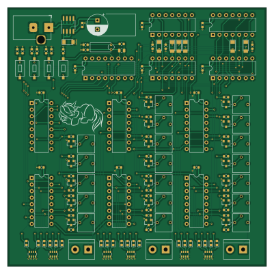
About the Ampmeter clock PCB
Ampmeter clock is an open source PCB design by Sirawit7205, published on GitHub under the CERN-OHL-S-2.0 license. It is a 4-layer board measuring 100 × 100 mm, with 147 components from 33 distinct parts.
Other key parts include the 4027, 40106, 4081, 4060 and 4510. By type, the board carries 44 resistors, 27 diodes, 20 transistors, 17 capacitors, 11 ICs and 4 switches.
From the project
CMOS chips driven analog ampmeter clock controller
This is an open-source KiCAD 5 design files for a logic chips-driven clock that output time on three ammeters.
This is a unique clock that will certainly impress people around you.
- Ammeter Output - Shows hour, minute, and second on three ammeters. - Works with both analog and digital meters. - Quartz Crystal-driven Clock with CD4060 IC - Design with logic ICs. Only need 11 chips for the circuit to work. - Set Hour, Set Min, Reset, and Clock Halt buttons - Ammeter adjustment trimpots - Aluminum Front Panel design available here
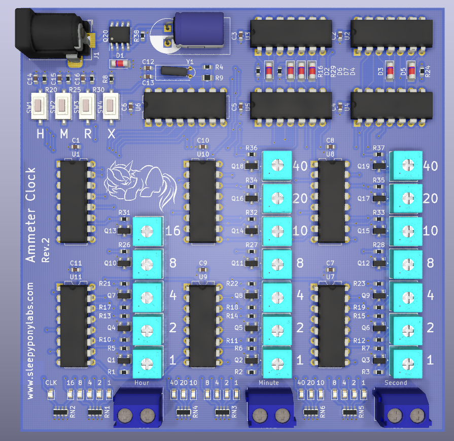
Main components on the Ampmeter clock
Ampmeter clock bill of materials (BOM)
147 components, 33 distinct parts.
| Qty | Part | Footprint | Refs |
|---|---|---|---|
| 1 | 4027 | DIP-16_W7.62mm | U1 |
| 2 | 40106 | DIP-14_W7.62mm | U2, U3 |
| 2 | 4081 | DIP-14_W7.62mm | U4, U5 |
| 1 | 4060 | DIP-16_W7.62mm | U6 |
| 2 | 4510 | DIP-16_W7.62mm | U7, U9 |
| 3 | 4516 | DIP-16_W7.62mm | U8, U10, U11 |
| 19 | 2N7002 | SOT-23 | Q1, Q2, Q3, Q4, Q5, Q6, Q7, Q8 +11 |
| 1 | NCE30P12S | SOIC-8_3.9x4.9mm_P1.27mm | Q20 |
| 1 | 32.768kHz | Crystal_Round_D2.0mm_Vertical | Y1 |
| 1 | Barrel_Jack_Switch | BarrelJack_Horizontal | J1 |
| 1 | HOUR | TerminalBlock_bornier-2_P5.08mm | MES1 |
| 1 | MINUTE | TerminalBlock_bornier-2_P5.08mm | MES2 |
| 1 | SECOND | TerminalBlock_bornier-2_P5.08mm | MES3 |
| 19 | 1k | 3362P_1 | RV1, RV2, RV3, RV4, RV5, RV6, RV7, RV8 +11 |
| 1 | SET_HOUR | TS-1101 | SW1 |
| 1 | SET_MIN | TS-1101 | SW2 |
| 1 | RESET | TS-1101 | SW3 |
| 1 | CLK_HALT | TS-1101 | SW4 |
| 1 | ZMM6V2 | D_MiniMELF | D1 |
| 6 | 1N4148 | D_MiniMELF | D2, D3, D4, D5, D6, D7 |
Show 13 more
| Qty | Part | Footprint | Refs |
|---|---|---|---|
| 20 | LED | LED_0603_1608Metric | D8, D9, D10, D11, D12, D13, D14, D15 +12 |
| 11 | 100nF | C_0603_1608Metric | C1, C2, C3, C4, C5, C6, C7, C8 +3 |
| 2 | 22pF | C_0603_1608Metric | C12, C13 |
| 3 | 1uF | C_0603_1608Metric | C14, C15, C16 |
| 1 | 470uF | CP_Radial_D8.0mm_P3.50mm | C17 |
| 10 | 4k7 | R_0603_1608Metric | R1, R2, R3, R8, R16, R20, R24, R25 +2 |
| 1 | 470k | R_0603_1608Metric | R4 |
| 19 | 100R | R_0603_1608Metric | R5, R6, R7, R13, R14, R15, R21, R22 +11 |
| 1 | 10M | R_0805_2012Metric | R9 |
| 3 | 2k2 | R_0603_1608Metric | R10, R11, R12 |
| 3 | 1k | R_0603_1608Metric | R17, R18, R19 |
| 1 | 100k | R_0603_1608Metric | R38 |
| 6 | 4k7 | R_Array_Convex_4x0603 | RN1, RN2, RN3, RN4, RN5, RN6 |
Ampmeter clock design files
The KiCad project lives in the Sirawit7205/ampmeter-clock repository on GitHub; these links point at the commit this page was built from.
- Layoutampmeter_clock.kicad_pcb
Ampmeter clock: common questions
How big is the Ampmeter clock PCB?
The Ampmeter clock measures 100 × 100 mm, has 4 copper layers and is 1.6 mm thick.
How many components are on the Ampmeter clock?
147 components, from 33 distinct parts. The full bill of materials is listed on this page.
Where can I download the Ampmeter clock design files?
From the Sirawit7205/ampmeter-clock repository on GitHub, which has the KiCad layout; the links under Design files point to each one.
Can I use the Ampmeter clock design in my own project?
Yes, under the terms of its CERN-OHL-S-2.0 license, which Sirawit7205 chose for the repository.