
Adelheid Plus

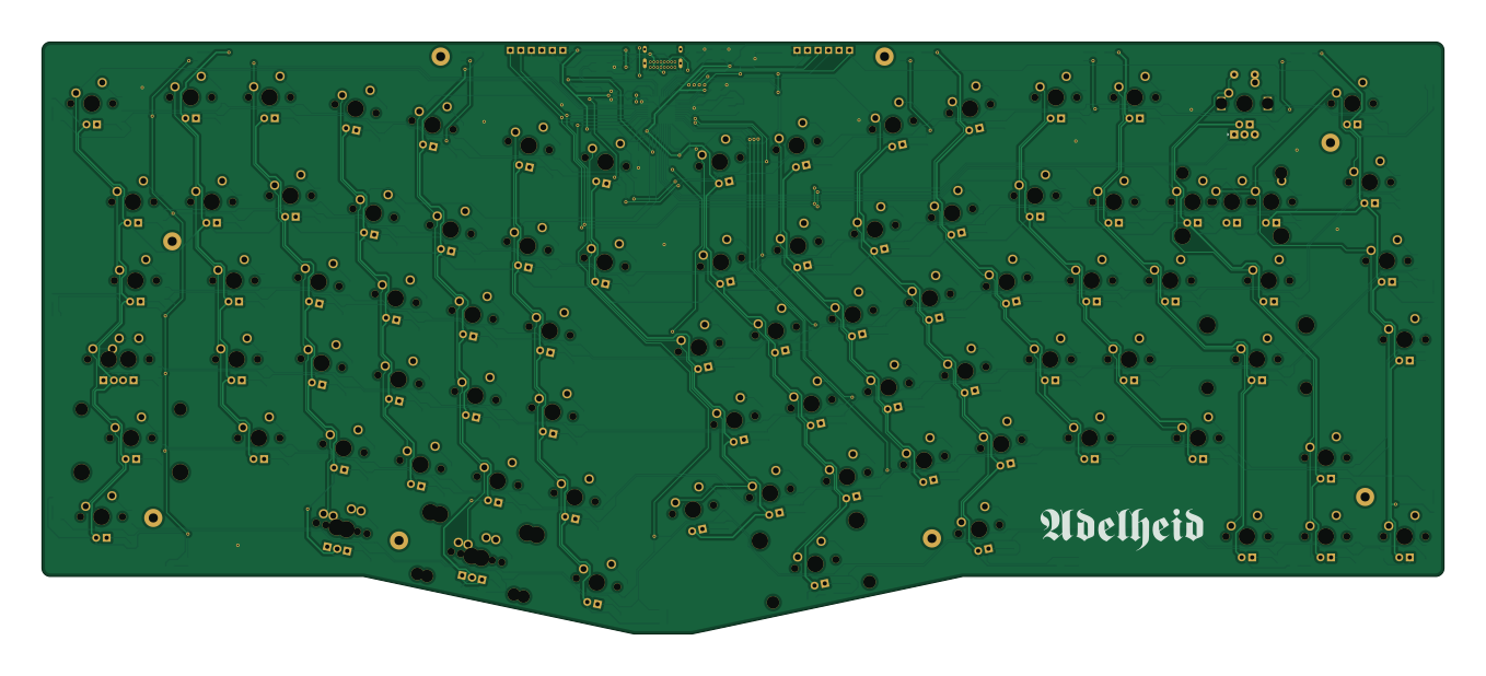
About the Adelheid Plus PCB
Adelheid Plus is an open source AVR/Arduino PCB design by Skycode22, published on GitHub. It is a 2-layer board measuring 339.1 × 143.2 mm, with 322 components from 41 distinct parts.
Its main chip is the ATMEGA32U4-MU, from the AVR/Arduino family. Other key parts include the USBLC6-2SC6. By type, the board carries 83 diodes, 17 speakers, 13 connectors, 9 capacitors, 5 resistors and 2 ICs.
It belongs with the keyboards designs in this gallery.
From the project
HID projects
The Adelheid Plus is a fork of Flookay's Adelheid case and PCB.
- pcb: KiCad files - pcb-mu: KiCad files for Atmega32u4-MU chip (same pinout as Atmega32u4-AU, but smaller footprint) - case: High profile case files - wrist-rest: Wrist rest files
I modifed the pcb a bit to accept an Atmega32u4-MU since those seem to be in stock more often.
- USB-C connector - Option for 2U backspace - Extra B key - Option for rotary encoder at F13 position - Option for 2.25U left space + 1.25U modifier combo (requires modification to plate)

Main components on the Adelheid Plus
Adelheid Plus bill of materials (BOM)
322 components, 41 distinct parts — part numbers from the project's BOM.
| Qty | Part | Footprint | Refs |
|---|---|---|---|
| 1 | USBLC6-2SC6 | SOT-23-6_Handsoldering | U1 |
| 1 | ATMEGA32U4-MU ATmega32U4-MU | QFN50P700X700X100-45N | U2 |
| 1 | 2N7002 | SOT-23 | Q1 |
| 1 | CRYSTAL_GND24 Crystal_GND24 | Crystal_SMD_SeikoEpson_FA238-4pin_3.2x2.5mm_HandSoldering | Y1 |
| 1 | USB_C_Receptacle_USB2.0 | USB_C_GCT_USB4085 | J1 |
| 1 | MISO | Pin_Header_Straight_1x01_Pitch2.54mm | J2 |
| 2 | VCC | Pin_Header_Straight_1x01_Pitch2.54mm | J3, J12 |
| 1 | SCK | Pin_Header_Straight_1x01_Pitch2.54mm | J4 |
| 1 | MOSI | Pin_Header_Straight_1x01_Pitch2.54mm | J5 |
| 1 | RES | Pin_Header_Straight_1x01_Pitch2.54mm | J6 |
| 2 | GND | Pin_Header_Straight_1x01_Pitch2.54mm | J7, J15 |
| 1 | PF4 | Pin_Header_Straight_1x01_Pitch2.54mm | J8 |
| 1 | PF5 | Pin_Header_Straight_1x01_Pitch2.54mm | J9 |
| 1 | D+ | Pin_Header_Straight_1x01_Pitch2.54mm | J13 |
| 1 | D- | Pin_Header_Straight_1x01_Pitch2.54mm | J14 |
| 17 | LED | LED_0805_2012Metric_Pad1.15x1.40mm_HandSolder | LS1, LS2, LS3, LS4, LS5, LS6, LS7, LS8 +9 |
| 72 | MX-LED | MXOnly-1U | MX1, MX2, MX7, MX8, MX9, MX10, MX11, MX12 +64 |
| 5 | MX-LED | MXOnly-1.5U | MX3, MX6, MX17, MX56, MX74 |
| 2 | MX-LED | MXOnly-1.75U | MX4, MX66 |
| 1 | MX-LED | MXOnly-1.75U-FLIPPED | MX4_1 |
Show 21 more
| Qty | Part | Footprint | Refs |
|---|---|---|---|
| 1 | MX-LED | MXOnly-2.25U | MX5 |
| 1 | MX-LED | MXOnly-1.25U | MX17.125 |
| 1 | MX-LED | MXOnly-2U-ReversedStabilizers | MX28 |
| 2 | MX-LED | MXOnly-2.25U-ReversedStabilizers | MX28.225, MX70 |
| 1 | MX-LED | MXOnly-2.75U-ReversedStabilizers | MX45 |
| 1 | MX-LED | MXOnly-2U | MX78_1 |
| 1 | Rotary_Encoder_Switch | RotaryEncoder_EC11 | RE_SW1 |
| 99 | C17798 R | R_0805_2012Metric_Pad1.15x1.40mm_HandSolder | RL1, RL2, RL3, RL4, RL5, RL6, RL7, RL8 +91 |
| 1 | R | R_0805_2012Metric_Pad1.20x1.40mm_HandSolder | RL34_1 |
| 2 | 5.1K | R_0805_2012Metric_Pad1.20x1.40mm_HandSolder | RU1, RU2 |
| 1 | SW_Push | SW_SPST_TL3342 | SWR1 |
| 82 | C81598 D | D_SOD-123 | D1, D2, D3, D4, D5, D6, D7, D8 +74 |
| 1 | D | D_SOD-123 | D34_1 |
| 2 | 22PF 22pF | C_0805_HandSoldering | C1, C2 |
| 1 | 10UF 10uF | C_0805_HandSoldering | C3 |
| 1 | C28323 1uF (±10%) | C_0805_HandSoldering | C4 |
| 1 | 1UF 1uF | C_0805_HandSoldering | C5 |
| 4 | 0.1UF 0.1uF | C_0805_HandSoldering | C6, C7, C8, C9 |
| 2 | 22 | R_0805_2012Metric_Pad1.15x1.40mm_HandSolder | R1, R2 |
| 2 | 10K | R_0805_2012Metric_Pad1.15x1.40mm_HandSolder | R3, R4 |
| 1 | 1.5K | R_0805_2012Metric_Pad1.15x1.40mm_HandSolder | R5 |
Adelheid Plus design files
The KiCad project lives in the Skycode22/HIDs repository on GitHub; these links point at the commit this page was built from.
Adelheid Plus: common questions
What microcontroller does the Adelheid Plus use?
The Adelheid Plus is built around the ATMEGA32U4-MU, from the AVR/Arduino family.
How big is the Adelheid Plus PCB?
The Adelheid Plus measures 339.1 × 143.2 mm, has 2 copper layers and is 1.6 mm thick.
How many components are on the Adelheid Plus?
322 components, from 41 distinct parts, with part numbers taken from the project's own BOM. The full bill of materials is listed on this page.
Where can I download the Adelheid Plus design files?
From the Skycode22/HIDs repository on GitHub, which has the KiCad layout and the BOM; the links under Design files point to each one.
Can I use the Adelheid Plus design in my own project?
The repository has no license, so all rights stay with Skycode22. Use it as a reference, and ask the author before reusing the design.
Can I test firmware for the Adelheid Plus without the hardware?
Yes. HardLabs builds a simulation of the board from its netlist and BOM, so you can run and debug AVR/Arduino firmware against it before you order a PCB.
More boards in HIDs
 AVR/Arduino
Mykeyboard
409 × 137 mm178 parts2LNo license132 AVR/Arduino
OOTstag rev2
409 × 137 mm170 parts2LNo license132 AVR/Arduino
Keyboard
364.9 × 108.3 mm40 parts2LNo license132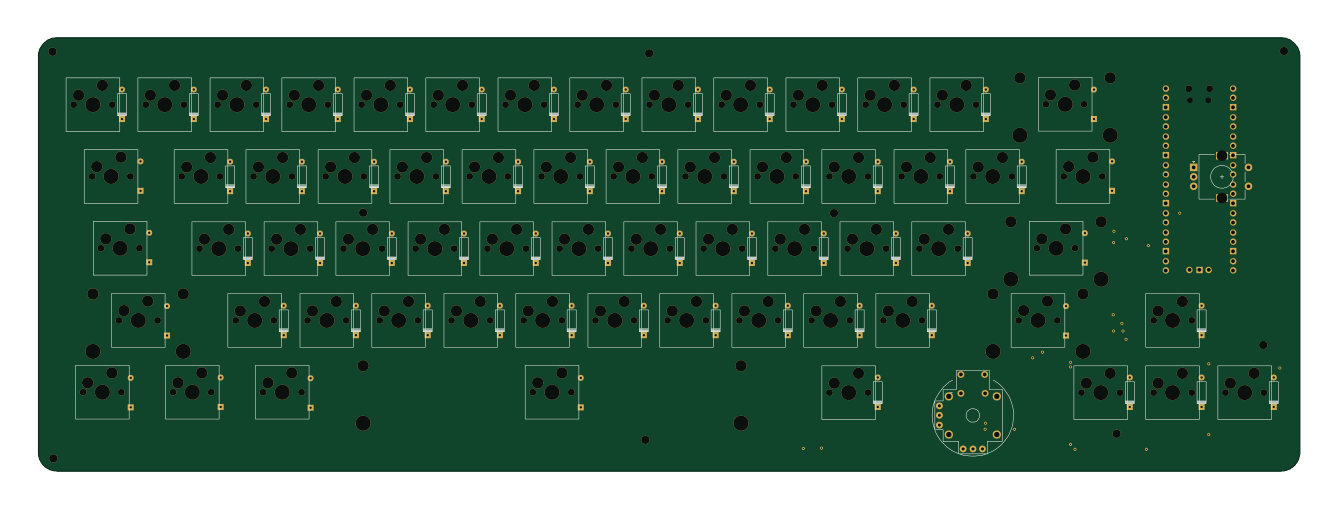
Keyjoy
333.9 × 114.7 mm32 parts2LNo license132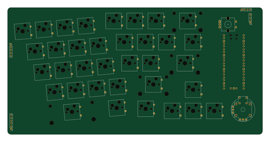
Split rev1
229.8 × 114.2 mm24 parts2LNo license132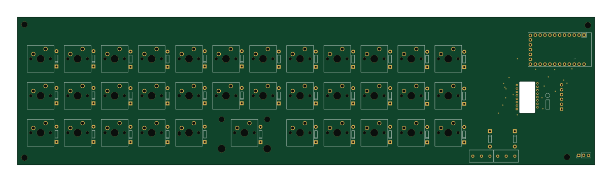 AVR/Arduino
Alpha29 pmw3360
301 × 77 mm14 parts2LNo license132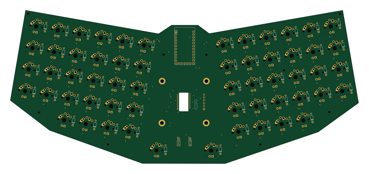 AVR/Arduino
Gigan rev2
305.9 × 135.1 mm14 parts2LNo license132
Similar boards
 AVR/Arduino
Redox keyboard
mattdibi
162.2 × 126.5 mm77 parts2LMIT2.0k AVR/Arduino
ModuleV450
stuartpittaway
30 × 61.4 mm39 parts2LCC-BY-NC-4.01.1k AVR/Arduino
V4
30 × 50 mm38 parts2LCC-BY-NC-4.01.1k AVR/Arduino
Discipline
coseyfannitutti
304.9 × 122.8 mm170 parts2LCC-BY-NC-4.01.0k AVR/Arduino
Megadesk
gcormier
41.7 × 32.2 mm23 parts2LGPL-3.0818 AVR/Arduino
Easyduino Atmega
Hanqaqa
68.8 × 53.6 mm35 parts4LCERN-OHL-P-2.0746