I2C-LCD-driver board hardware design

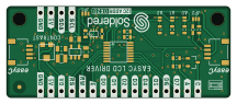
About the I2C-LCD-driver board hardware design
I2C-LCD-driver board hardware design is an open source PCB design by SolderedElectronics, published on GitHub under the TAPR-OHL-1.0 license. It is a 2-layer board measuring 54 × 22 mm, with 32 components from 19 distinct parts.
Other key parts include the TCA9534PWR, TPS613222A and NMOS-DUAL. By type, the board carries 10 resistors, 5 jumpers, 5 relays, 5 capacitors, 3 ICs and 1 transistor.
It belongs with the displays & leds designs in this gallery.
From the project
Hardware design, BOM, gerbers and 3D files for I2C-LCD-driver-board designed by Soldered Electronics.
This adapter makes connection of LCD to Dasduino (or any other Arduino-compatible board) a breeze! It uses I2C communication which needs only two pins. It can be used and work with all of ours LCDs (16x2, 20x4, 16x4). Use our library and get started in few minutes of work!
It's even easier with easyC - no soldering is needed!
All Soldered Electronics hardware designed in KiCAD, and repositories are organized in the following way:
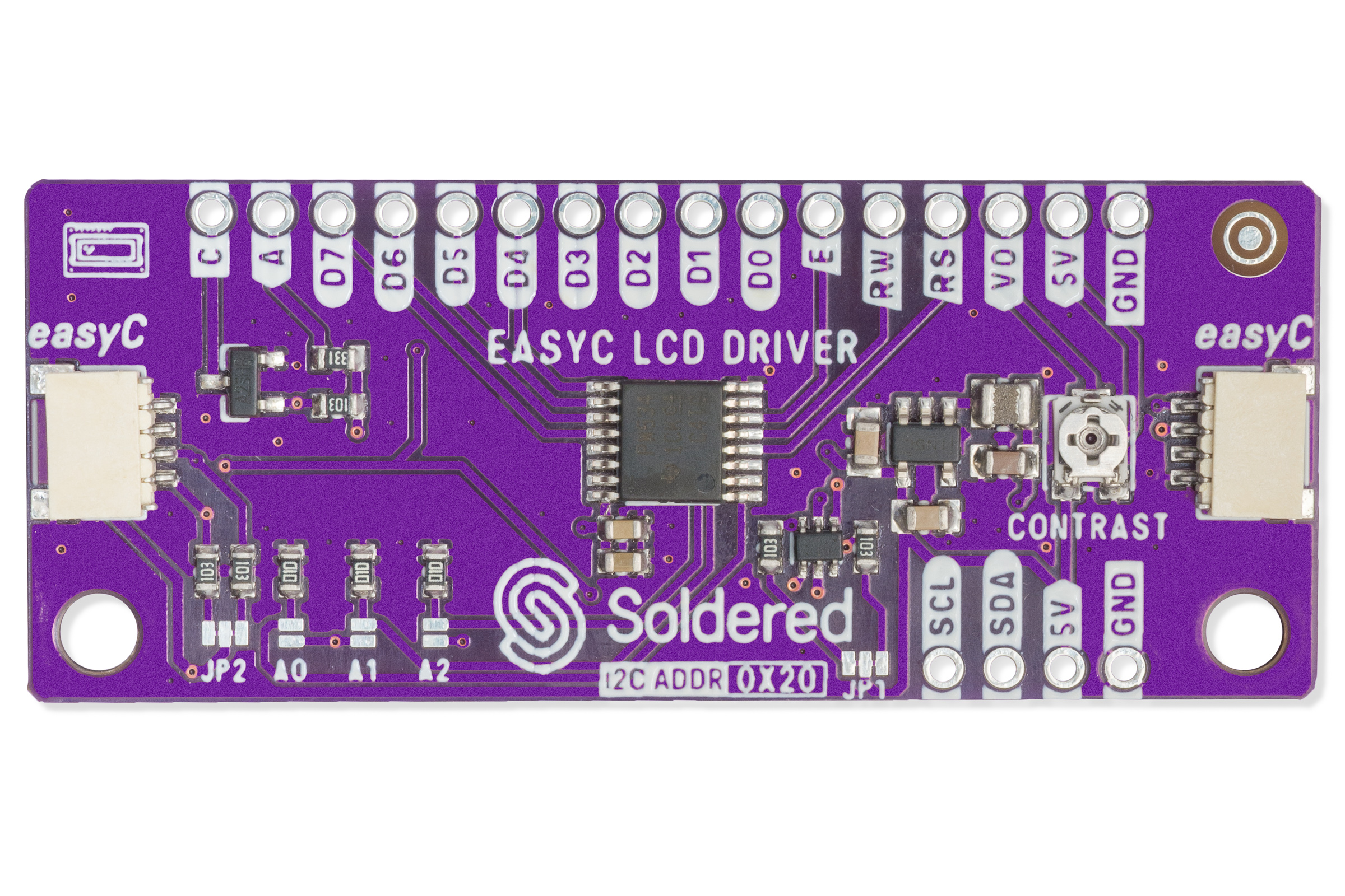
Main components on the I2C-LCD-driver board hardware design
I2C-LCD-driver board hardware design bill of materials (BOM)
32 components, 19 distinct parts — part numbers from the project's BOM.
| Qty | Part | Footprint | Refs |
|---|---|---|---|
| 1 | TCA9534PWR | TSSOP-16 | U1 |
| 1 | TPS613222A | tps613222a | U2 |
| 1 | NMOS-DUAL | SOT-363 | U3 |
| 1 | NMOS | SOT-23-3 | Q1 |
| 2 | HOLE_3.2mm | HOLE_3.2mm | H1, H2 |
| 2 | SMD_JUMPER_3_PAD_TRACE | SMD_JUMPER_3_PAD_TRACE | JP1, JP2 |
| 3 | SMD_JUMPER | SMD_JUMPER | JP3, JP4, JP5 |
| 2 | easyC-SMD | easyC-connector | K1, K2 |
| 2 | HEADER_MALE_8X1 | HEADER_MALE_8X1 | K3, K4 |
| 1 | HEADER_MALE_4X1 | HEADER_MALE_4X1 | K5 |
| 1 | DFE201612E-2R2M=P2 | 0806L | L1 |
| 2 | CL10A226MPCNUBE | 0805C | C1, C2 |
| 1 | 1u | 0603C | C3 |
| 1 | 100n | 0603C | C4 |
| 1 | C1608X7S1A475K080AC | 0805C | C5 |
| 3 | 100k | 0603R | R1, R2, R3 |
| 5 | 10k | 0603R | R4, R6, R8, R9, R10 |
| 1 | 0R | 0603R | R5 |
| 1 | tc33x-2-103e | tc33x-2-103e | R7 |
I2C-LCD-driver board hardware design design files
The KiCad project lives in the SolderedElectronics/I2C-LCD-driver-board-hardware-design repository on GitHub; these links point at the commit this page was built from.
I2C-LCD-driver board hardware design: common questions
How big is the I2C-LCD-driver board hardware design?
The I2C-LCD-driver board hardware design measures 54 × 22 mm, has 2 copper layers and is 1.6 mm thick.
How many components are on the I2C-LCD-driver board hardware design?
32 components, from 19 distinct parts, with part numbers taken from the project's own BOM. The full bill of materials is listed on this page.
Where can I download the I2C-LCD-driver board hardware design design files?
From the SolderedElectronics/I2C-LCD-driver-board-hardware-design repository on GitHub, which has the KiCad layout, the schematic and the BOM; the links under Design files point to each one.
Can I use the I2C-LCD-driver board hardware design design in my own project?
Yes, under the terms of its TAPR-OHL-1.0 license, which SolderedElectronics chose for the repository.
 atopile


 AxxAxx
 eez-open