
Stepper motor driver-DRV8825-board hardware design

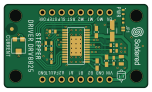
About the Stepper motor driver-DRV8825-board hardware design
Stepper motor driver-DRV8825-board hardware design is an open source PCB design by SolderedElectronics, published on GitHub under the TAPR-OHL-1.0 license. It is a 2-layer board measuring 38 × 22 mm, with 23 components from 15 distinct parts.
Other key parts include the DRV8825. By type, the board carries 8 resistors, 6 capacitors, 2 relays, 1 IC, 1 jumper and 1 diode.
It belongs with the robotics & motion designs in this gallery.
From the project
Hardware design, BOM, gerbers and 3D files for Stepper-motor-driver-DRV8825-board designed by Soldered Electronics.
The stepper motor driver enables very precise control of the stepper motor. The DRV8825, located on this board, enables microstepping of a bipolar motor with an adjustable current limit, overcurrent and overtemperature protection. Controls steps up to 1/32 step. It has a potentiometer for setting the desired current.
This repository contains all design files for Stepper motor driver DRV8825 board, organized as follows:

Main components on the Stepper motor driver-DRV8825-board hardware design
Stepper motor driver-DRV8825-board hardware design bill of materials (BOM)
23 components, 15 distinct parts — part numbers from the project's BOM.
| Qty | Part | Footprint | Refs |
|---|---|---|---|
| 1 | DRV8825 | DRV8825 | U1 |
| 4 | HOLE_3.2mm | HOLE_3.2mm | H1, H2, H3, H4 |
| 1 | SMD-JUMPER-CONNECTED_TRACE_SLODERMASK | SMD-JUMPER-CONNECTED_TRACE_SLODERMASK | JP1 |
| 2 | HEADER_MALE_8X1 | HEADER_MALE_8X1 | K1, K2 |
| 1 | purple | 0402LED | D1 |
| 1 | 12101C335K4T2A | 1210C | C1 |
| 3 | CL21B104KCFNNNE | 0805C | C2, C3, C4 |
| 1 | 08051C103KAT2A | 0805C | C5 |
| 1 | 0.47uF | 0603C | C6 |
| 2 | 73L2R20G | 0603R | R1, R3 |
| 1 | 1M | 0603R | R2 |
| 1 | tc33x-2-104e | tc33x-2-103e | R4 |
| 1 | 1.5k | 0603R | R5 |
| 2 | 10k | 0603R | R6, R8 |
| 1 | 2k2 | 0402R | R7 |
Stepper motor driver-DRV8825-board hardware design design files
The KiCad project lives in the SolderedElectronics/Stepper-motor-driver-DRV8825-board-hardware-design repository on GitHub; these links point at the commit this page was built from.
Stepper motor driver-DRV8825-board hardware design: common questions
How big is the Stepper motor driver-DRV8825-board hardware design?
The Stepper motor driver-DRV8825-board hardware design measures 38 × 22 mm, has 2 copper layers and is 1.6 mm thick.
How many components are on the Stepper motor driver-DRV8825-board hardware design?
23 components, from 15 distinct parts, with part numbers taken from the project's own BOM. The full bill of materials is listed on this page.
Where can I download the Stepper motor driver-DRV8825-board hardware design design files?
From the SolderedElectronics/Stepper-motor-driver-DRV8825-board-hardware-design repository on GitHub, which has the KiCad layout, the schematic and the BOM; the links under Design files point to each one.
Can I use the Stepper motor driver-DRV8825-board hardware design design in my own project?
Yes, under the terms of its TAPR-OHL-1.0 license, which SolderedElectronics chose for the repository.
Similar boards

Cube batteryboard
willem-pennings
95 × 95 mm4 parts2LGPL-3.01.1k
Rp2040 encoder
Twisted-Fields
36.7 × 33.3 mm10 parts2LCustom license417
VESC Controller
paltatech
160 × 90 mm908 parts2LNo license354
${BOARD NAME} Assembly
EPFLXplore
45 × 43.5 mm21 parts4LApache-2.0345
OpenESC-20x20
OpenDrone-hw
31.2 × 33 mm180 parts6LCERN-OHL-S-2.0243
Legacy stepper motor analyzer
zapta
96.7 × 66.4 mm28 parts2LCC0-1.0163