
Si4735Board

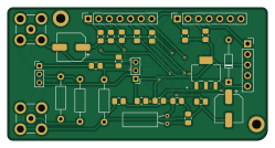
About the Si4735Board PCB
Si4735Board is an open source PCB design by SREERAJSVT, published on GitHub. It is a 2-layer board measuring 62.2 × 31.8 mm, with 31 components from 16 distinct parts.
Other key parts include the AP2114H-3.3TRG1 and SI4735-D60-GU. By type, the board carries 11 capacitors, 7 connectors, 6 resistors, 3 inductors, 2 ICs and 1 crystal.
It belongs with the rf & radio, displays & leds and power & battery designs in this gallery.
From the project
This project details the design and development of a Si4732/Si4735 based radio receiver utilizing a Raspberry Pi Pico for control and a custom-designed PCB
Below is a clean, corrected, and professional rewrite of your README, with naming fixes, consistency improvements, and hyperlink validation/cleanup. I’ve kept it GitHub-ready, clear for open-source users, and suitable for OSHW platforms.
Open-Source Si4732 / Si4735 Radio Receiver with Raspberry Pi Pico Front End
This project documents the design and development of a modular Si4732 / Si4735–based radio receiver, controlled by a Raspberry Pi Pico and implemented on a custom, fully open-source PCB platform.
Main components on the Si4735Board
Si4735Board bill of materials (BOM)
31 components, 16 distinct parts.
| Qty | Part | Footprint | Refs |
|---|---|---|---|
| 1 | AP2114H-3.3TRG1 | SOT-223_DIO | U1 |
| 1 | SI4735-D60-GU RECEVIER-SI4735-D60-GU_SSOP24_ | SSOP-24_3.9x8.7mm_P0.635mm | U2 |
| 1 | 32.768KHz | Crystal_C38-LF_D3.0mm_L8.0mm_Horizontal | Y1 |
| 1 | FMI | SMB_Jack_Vertical | J1 |
| 1 | Conn_01x05_Pin | PinSocket_1x05_P2.54mm_Vertical | J2 |
| 2 | SPI_D | PinSocket_1x07_P2.54mm_Vertical | J3, J4 |
| 1 | AMI | SMB_Jack_Vertical | J5 |
| 1 | 35 ANT | PinHeader_1x03_P2.00mm_Vertical | J6 |
| 1 | SEN | PinHeader_1x03_P2.00mm_Vertical | J7 |
| 1 | 1N5817 | D_DO-34_SOD68_P10.16mm_Horizontal | D1 |
| 3 | 180-450uH | L_Axial_L5.3mm_D2.2mm_P10.16mm_Horizontal_Vishay_IM-1 | L1, L2, L3 |
| 5 | 104 | C_0805_2012Metric_Pad1.18x1.45mm_HandSolder | C1, C3, C5, C6, C7 |
| 2 | 100uF | CP_Elec_6.3x5.9 | C2, C4 |
| 4 | 22pF | C_0805_2012Metric_Pad1.18x1.45mm_HandSolder | C8, C9, C10, C11 |
| 5 | 10K | R_0805_2012Metric_Pad1.20x1.40mm_HandSolder | R1, R2, R3, R4, R7 |
| 1 | 2.2K | R_0805_2012Metric_Pad1.20x1.40mm_HandSolder | R5 |
Si4735Board design files
The KiCad project lives in the SREERAJSVT/SiSeriesRadio repository on GitHub; these links point at the commit this page was built from.
Si4735Board: common questions
How big is the Si4735Board PCB?
The Si4735Board measures 62.2 × 31.8 mm, has 2 copper layers and is 1.6 mm thick.
How many components are on the Si4735Board?
31 components, from 16 distinct parts. The full bill of materials is listed on this page.
Where can I download the Si4735Board design files?
From the SREERAJSVT/SiSeriesRadio repository on GitHub, which has the KiCad layout and the schematic; the links under Design files point to each one.
Can I use the Si4735Board design in my own project?
The repository has no license, so all rights stay with SREERAJSVT. Use it as a reference, and ask the author before reusing the design.
More boards in SiSeriesRadio
Similar boards
BM28B0.6-24DSBreakout
scottbez1
15.2 × 35.6 mm3 parts2LApache-2.022.2k
LevelShifterBreakout
15.2 × 20.3 mm5 parts2LApache-2.022.2k
View base
81.2 × 81.2 mm81 parts2LApache-2.022.2k
View screen
35 × 35 mm12 parts2LApache-2.022.2k
Display eval
byrantech
52.1 × 22.6 mm12 parts4LMIT4.3k
ChainlinkBase
98.4 × 190.5 mm119 parts2LApache-2.04.2k