
555 Badge

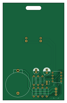
About the 555 Badge PCB
555 Badge is an open source PCB design by Sreeram-Ramesh, published on GitHub under the MIT license. It is a 2-layer board measuring 53.9 × 85.6 mm, with 15 components from 12 distinct parts.
Other key parts include the 7555. By type, the board carries 7 resistors, 2 diodes, 2 capacitors, 1 IC, 1 transistor and 1 switch.
It belongs with the wearables designs in this gallery.
From the project
An archive for my KiCad project folders.
An archive for all my KiCad project folders for various projects I've been working on. Find more about each of these KiCad projects on their respective repos if they exist wherein I have shared about the project itself, here's a quick overview of my KiCad designs.
Several attempts were made by me in the past to try out designing and printing PCBs for my personal high school projects. After constant yapping and getting my dad on-board for my PCB fab through JLC PCB, results were pretty bad cuz of my PCB design skills. Some pictures for context. Fast forwarding now, I understood high-school me…
Main components on the 555 Badge
555 Badge bill of materials (BOM)
15 components, 12 distinct parts.
| Qty | Part | Footprint | Refs |
|---|---|---|---|
| 1 | 7555 | ICM7555-PDIP | U1 |
| 1 | 2N3904 | TO-92-3 | Q1 |
| 1 | BS-7 MPD (Memory Protection Devices) | Battery_Holder_Coin_2032_BS-7 | BAT1 |
| 1 | EG1218 E-Switch | Switch_Slide_11.6x4mm_EG1218 | S1 |
| 2 | RED | LED_D3.0mm | D1, D2 |
| 1 | 10uF | CP_Radial_D5.0mm_P2.00mm | C1 |
| 1 | 100uF | CP_Radial_D6.3mm_P2.50mm | C2 |
| 2 | 22k | R_Axial_DIN0207_L6.3mm_D2.5mm_P7.62mm_Horizontal | R1, R3 |
| 1 | 330k | R_Axial_DIN0207_L6.3mm_D2.5mm_P7.62mm_Horizontal | R2 |
| 1 | 100k | R_Axial_DIN0207_L6.3mm_D2.5mm_P7.62mm_Horizontal | R4 |
| 1 | 10k | R_Axial_DIN0207_L6.3mm_D2.5mm_P7.62mm_Horizontal | R5 |
| 2 | 100 | R_Axial_DIN0207_L6.3mm_D2.5mm_P7.62mm_Horizontal | R6, R7 |
555 Badge design files
The KiCad project lives in the Sreeram-Ramesh/KiCad-Projects repository on GitHub; these links point at the commit this page was built from.
- Layout555Badge/555Badge.kicad_pcb
- Schematic555Badge/555Badge.kicad_sch
555 Badge: common questions
How big is the 555 Badge PCB?
The 555 Badge measures 53.9 × 85.6 mm, has 2 copper layers and is 1.6 mm thick.
How many components are on the 555 Badge?
15 components, from 12 distinct parts. The full bill of materials is listed on this page.
Where can I download the 555 Badge design files?
From the Sreeram-Ramesh/KiCad-Projects repository on GitHub, which has the KiCad layout and the schematic; the links under Design files point to each one.
Can I use the 555 Badge design in my own project?
Yes, under the terms of its MIT license, which Sreeram-Ramesh chose for the repository.
More boards in KiCad-Projects
Similar boards
BM28B0.6-24DSBreakout
scottbez1
15.2 × 35.6 mm3 parts2LApache-2.022.2k
LevelShifterBreakout
15.2 × 20.3 mm5 parts2LApache-2.022.2k
View screen
35 × 35 mm12 parts2LApache-2.022.2k
View base
81.2 × 81.2 mm81 parts2LApache-2.022.2k
ChainlinkBase
98.4 × 190.5 mm119 parts2LApache-2.04.2k
ChainlinkDriverTester
198.1 × 95.3 mm123 parts2LApache-2.04.2k