
HB-MOD-UART-USB

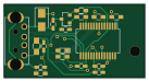
About the HB-MOD-UART-USB PCB
HB-MOD-UART-USB is an open source PCB design by stan23, published on GitHub under the CC-BY-NC-4.0 license. It is a 2-layer board measuring 34.3 × 17.8 mm, with 20 components from 15 distinct parts.
Other key parts include the FT232RL and HM-MOD-UART. By type, the board carries 8 capacitors, 6 resistors, 2 ICs, 1 transistor, 1 connector and 1 diode.
It belongs with the iot & wireless designs in this gallery.
From the project
Verschiedene Platinen für HomeMatic, AskSinPP und SmartHome
❗ Inzwischen unterstützt eQ-3s HmIP-RFUSB sowohl HM- als auch HmIP-Geräte und ist eine einfache Alternative.
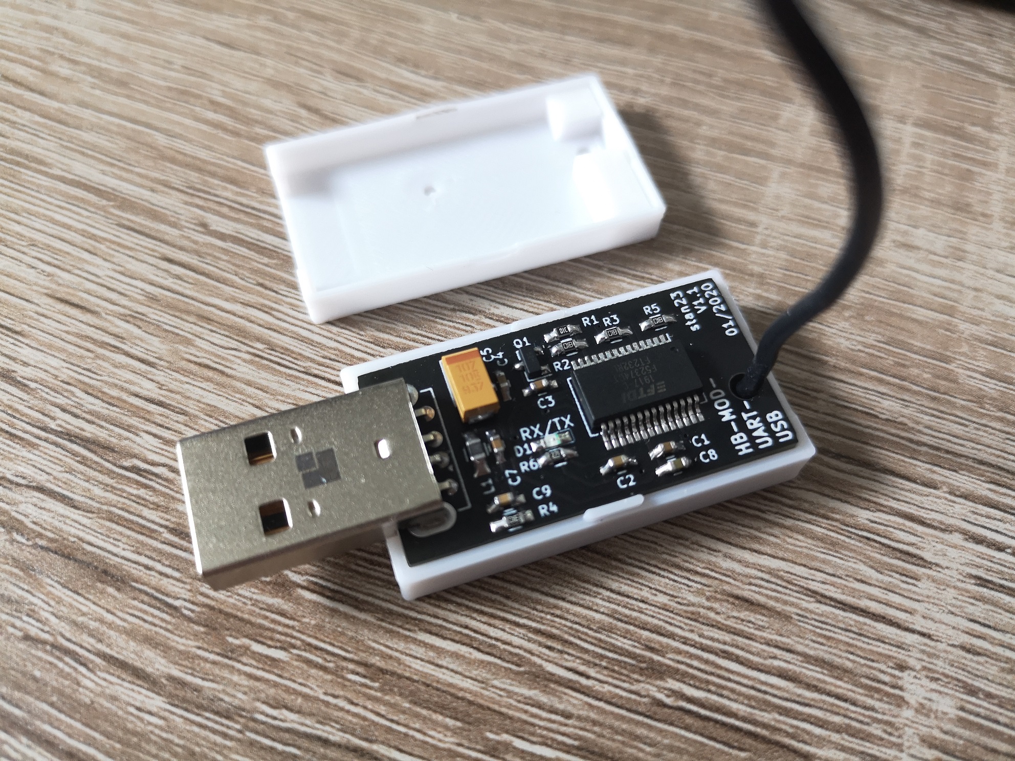
Main components on the HB-MOD-UART-USB
HB-MOD-UART-USB bill of materials (BOM)
20 components, 15 distinct parts.
| Qty | Part | Footprint | Refs |
|---|---|---|---|
| 1 | FT232RL | SSOP-28_5.3x10.2mm_Pitch0.65mm_Handsoldering | U1 |
| 1 | HM-MOD-UART | HM-MOD-UART_SMD | U2 |
| 1 | IRLML6402 | SOT-23 | Q1 |
| 1 | USB | USB_A | J1 |
| 1 | RX/TX | LED_0603_HandSoldering | D1 |
| 1 | Ferrite Bead | L_0805_HandSoldering | L1 |
| 4 | 100nF | C_0603_HandSoldering | C1, C2, C3, C4 |
| 1 | 100u / 10V | CP_Tantalum_Case-B_EIA-3528-21_Wave | C5 |
| 1 | 10nF | C_0603_HandSoldering | C7 |
| 1 | 4.7uF | C_0603_HandSoldering | C8 |
| 1 | 4.7nF | C_0603_HandSoldering | C9 |
| 1 | 10K | R_0603_HandSoldering | R1 |
| 3 | 1k | R_0603_HandSoldering | R2, R3, R5 |
| 1 | 1M | R_0603_HandSoldering | R4 |
| 1 | 270 | R_0603_HandSoldering | R6 |
HB-MOD-UART-USB design files
The KiCad project lives in the stan23/myPCBs repository on GitHub; these links point at the commit this page was built from.
HB-MOD-UART-USB: common questions
How big is the HB-MOD-UART-USB PCB?
The HB-MOD-UART-USB measures 34.3 × 17.8 mm, has 2 copper layers and is 1.6 mm thick.
How many components are on the HB-MOD-UART-USB?
20 components, from 15 distinct parts. The full bill of materials is listed on this page.
Where can I download the HB-MOD-UART-USB design files?
From the stan23/myPCBs repository on GitHub, which has the KiCad layout; the links under Design files point to each one.
Can I use the HB-MOD-UART-USB design in my own project?
It is published under CC-BY-NC-4.0, which limits how it may be reused; read the license before building on it.
More boards in myPCBs
 AVR/Arduino
HB-LC-Dim6PWM-CV
139 × 56.3 mm57 parts2LCC-BY-NC-4.021 ESP32
AskSinAnalyzer
92.5 × 61.2 mm53 parts2LCC-BY-NC-4.021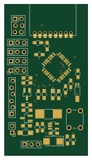 AVR/Arduino
HB-UNI-Sen-CAP-MOIST
32 × 58 mm38 parts2LCC-BY-NC-4.021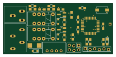 AVR/Arduino
HM-LC-Bl1-FM-DC
59.7 × 27.9 mm34 parts2LCC-BY-NC-4.021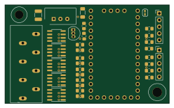
HB-LC-Dim5PWM-CV AskSinDuino32Shield
62 × 37.4 mm34 parts2LCC-BY-NC-4.021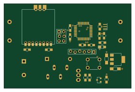 AVR/Arduino
HB-Mower-Fence
69.9 × 46.2 mm30 parts2LCC-BY-NC-4.021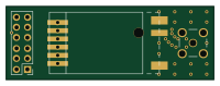
HB-MOD-UART
50 × 17.8 mm7 parts2LCC-BY-NC-4.021
Similar boards
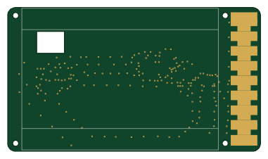
EinkPDA screen
TalismanDesign
95 × 54 mm27 parts2LApache-2.02.0k
RPi RM0 WiFi/Bluetooth Module
schlae
11.1 × 14 mm76 parts6LNo license1.0k
L0 USB
Luos-io
20.3 × 15.3 mm19 parts2LMIT547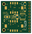
Breakout board
26.7 × 27.9 mm29 parts2LMIT547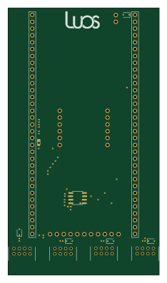
Stm32f0 disco Luos shield
55.9 × 99.1 mm26 parts2LMIT547
L0 USBA
20.3 × 15.3 mm19 parts2LMIT547