
Akashi-18

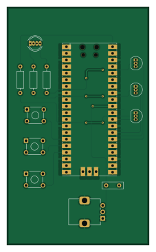
About the Akashi-18 PCB
Akashi-18 is an open source RP2040/RP2350 PCB design by suikan4github, published on GitHub under the MIT license. It is a 2-layer board measuring 54.6 × 91.4 mm, with 13 components from 9 distinct parts.
Its main chip is the Pico, from the RP2040/RP2350 family. By type, the board carries 3 transistors, 3 switches, 3 resistors, 1 IC, 1 diode and 1 capacitor.
From the project
Raspberry Pi Pico board with full colar LED.
The PCB employs followings : Parts | QTY -------------------|----- Full Color LED | 1 Push button Switch | 3 Potentiometer | 1
The following table shows the pin connections.
Color | GPIO ------|-------- Red | 20 Green | 21 Blue | 22
Each GPIO is active Hi. That means, Output "H" signal to turn on the LED.
Switch | GPIO -------|------ SW1 | 11 SW2 | 12 SW3 | 13
All switches are active Lo. That means, pushing down the switch makes the GPIO input to "L".
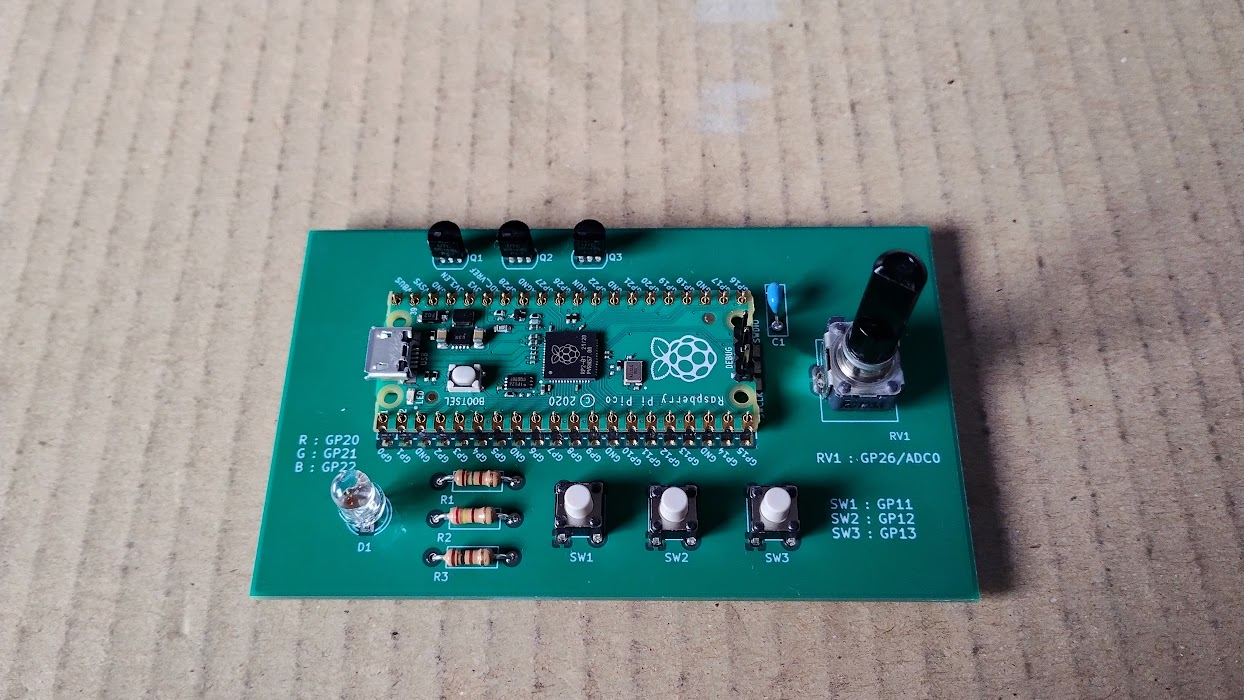
Main components on the Akashi-18
Akashi-18 bill of materials (BOM)
13 components, 9 distinct parts.
| Qty | Part | Footprint | Refs |
|---|---|---|---|
| 1 | Pico | RPi_Pico_SMD_TH | U1 |
| 3 | DTC143Z | TO-92_Inline | Q1, Q2, Q3 |
| 1 | RK09D117000C | Potentiometer_Alps_RK09K_Single_Vertical | RV1 |
| 3 | B3FS | SW_TH_Tactile_Omron_B3F-10xx | SW1, SW2, SW3 |
| 1 | OSTAMA5B31A | LED_D5.0mm-4_RGB | D1 |
| 1 | 0.1u | C_Disc_D8.0mm_W2.5mm_P5.00mm | C1 |
| 1 | 150 | R_Axial_DIN0207_L6.3mm_D2.5mm_P10.16mm_Horizontal | R1 |
| 1 | 240 | R_Axial_DIN0207_L6.3mm_D2.5mm_P10.16mm_Horizontal | R2 |
| 1 | 91 | R_Axial_DIN0207_L6.3mm_D2.5mm_P10.16mm_Horizontal | R3 |
Akashi-18 design files
The KiCad project lives in the suikan4github/Akashi-18 repository on GitHub; these links point at the commit this page was built from.
- LayoutAkashi-18.kicad_pcb
- SchematicAkashi-18.kicad_sch
Akashi-18: common questions
What microcontroller does the Akashi-18 use?
The Akashi-18 is built around the Pico, from the RP2040/RP2350 family.
How big is the Akashi-18 PCB?
The Akashi-18 measures 54.6 × 91.4 mm, has 2 copper layers and is 1.6 mm thick.
How many components are on the Akashi-18?
13 components, from 9 distinct parts. The full bill of materials is listed on this page.
Where can I download the Akashi-18 design files?
From the suikan4github/Akashi-18 repository on GitHub, which has the KiCad layout and the schematic; the links under Design files point to each one.
Can I use the Akashi-18 design in my own project?
Yes, under the terms of its MIT license, which suikan4github chose for the repository.
Can I test firmware for the Akashi-18 without the hardware?
Yes. HardLabs builds a simulation of the board from its netlist and BOM, so you can run and debug RP2040/RP2350 firmware against it before you order a PCB.
Similar boards
 RP2040/RP2350
OSO-BOOK-C1
joeycastillo
85 × 115 mm29 parts2LCC-BY-SA-4.08.1k RP2040/RP2350
Corne cherry
foostan
277.2 × 107.5 mm164 parts2LCC-BY-4.07.7k RP2040/RP2350
Corne chocolate
277.2 × 107.5 mm164 parts2LCC-BY-4.07.7k RP2040/RP2350
Jitx design
gusmanb
55.5 × 65 mm26 parts4LGPL-3.05.0k RP2040/RP2350
LogicAnalyzer
57 × 55.2 mm6 parts2LGPL-3.05.0k RP2040/RP2350
Main
google
98 × 71 mm102 parts2LApache-2.02.9k