
C64-Joystick-Switcher

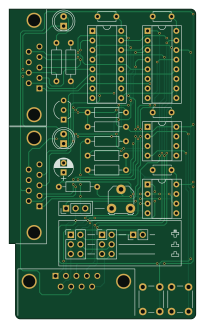
About the C64-Joystick-Switcher PCB
C64-Joystick-Switcher is an open source PCB design by tebl, published on GitHub under the CERN-OHL-1.2 license. It is a 2-layer board measuring 49.3 × 81.9 mm, with 27 components from 18 distinct parts.
Other key parts include the 74HCT4053 and NE555. By type, the board carries 8 resistors, 5 capacitors, 4 ICs, 2 connectors, 2 jumpers and 2 switches.
It belongs with the retro computing designs in this gallery.
From the project
Wanted a joystick switcher for my Commodore 64, so I built one by adapting C64 Mega Switcher for use with Atari-style joysticks. Supports secondary fire-button when using Sega Master System gamepads, even includes an auto-fire circuit.
Start by studying the PCB, both sides and perform dry fits to see that you have an idea of where everything goes since removing things is always a lot harder than getting it right in the first place (match orientation to symbols, see gallery images for reference if you're unsure). The diodes are installed standing, the stripe goes into the board so that it is laying directly against the board - a hint for making these look pretty, is wrapping one of the wires around a small screwdriver to get the loops looking almost identical!
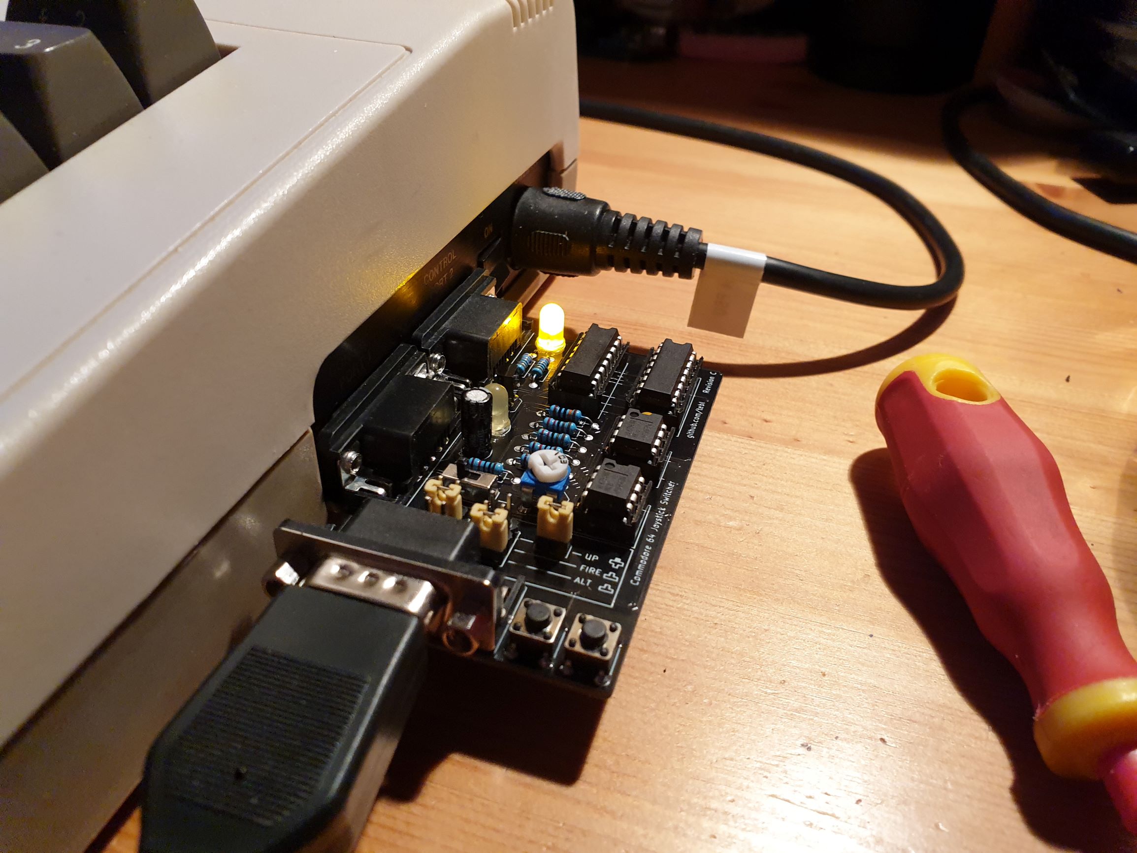
Main components on the C64-Joystick-Switcher
C64-Joystick-Switcher bill of materials (BOM)
27 components, 18 distinct parts.
| Qty | Part | Footprint | Refs |
|---|---|---|---|
| 2 | 74HCT4053 | DIP-16_W7.62mm_Socket | U1, U2 |
| 2 | NE555 | DIP-8_W7.62mm_Socket | U3, U4 |
| 1 | BC547 | TO-92_Inline_Wide | Q1 |
| 1 | B2_SEL | Pin_Header_Straight_2x03_Pitch2.54mm | J4 |
| 1 | B1_SEL | Pin_Header_Straight_2x03_Pitch2.54mm | J5 |
| 1 | UP | Pin_Header_Straight_1x02_Pitch2.54mm | JP1 |
| 1 | AUTOFIRE | Pin_Header_Straight_1x03_Pitch2.54mm | JP2 |
| 1 | 10k | Potentiometer_Triwood_RM-065 | RV1 |
| 1 | P1_SEL | SW_PUSH_6mm | SW1 |
| 1 | P2_SEL | SW_PUSH_6mm | SW2 |
| 1 | P2_LED | LED_D5.0mm | D1 |
| 1 | P1_LED | LED_D5.0mm | D2 |
| 4 | 100nF | C_Disc_D4.7mm_W2.5mm_P5.00mm | C1, C2, C3, C4 |
| 1 | 10uF | CP_Radial_D5.0mm_P2.50mm | C5 |
| 3 | 10k | R_Axial_DIN0207_L6.3mm_D2.5mm_P10.16mm_Horizontal | R1, R2, R9 |
| 2 | 220 | R_Axial_DIN0207_L6.3mm_D2.5mm_P10.16mm_Horizontal | R3, R4 |
| 2 | 2k2 | R_Axial_DIN0207_L6.3mm_D2.5mm_P10.16mm_Horizontal | R5, R7 |
| 1 | 100k | R_Axial_DIN0207_L6.3mm_D2.5mm_P10.16mm_Horizontal | R6 |
C64-Joystick-Switcher design files
The KiCad project lives in the tebl/C64-Joystick-Switcher repository on GitHub; these links point at the commit this page was built from.
C64-Joystick-Switcher: common questions
How big is the C64-Joystick-Switcher PCB?
The C64-Joystick-Switcher measures 49.3 × 81.9 mm, has 2 copper layers and is 1.6 mm thick.
How many components are on the C64-Joystick-Switcher?
27 components, from 18 distinct parts. The full bill of materials is listed on this page.
Where can I download the C64-Joystick-Switcher design files?
From the tebl/C64-Joystick-Switcher repository on GitHub, which has the KiCad layout; the links under Design files point to each one.
Can I use the C64-Joystick-Switcher design in my own project?
Yes, under the terms of its CERN-OHL-1.2 license, which tebl chose for the repository.
Similar boards
Amiga External
hoglet67
21.9 × 76.7 mm6 parts2LGPL-3.01.0k
Atari pickup
26.4 × 53.9 mm7 parts2LGPL-3.01.0k
Deniseadapter
26.7 × 62.2 mm16 parts2LGPL-3.01.0k
Analog
53.9 × 23.2 mm33 parts2LGPL-3.01.0k
Rgb to hdmi
77 × 97 mm67 parts2LGPL-3.01.0k
Buffer
53.9 × 23.2 mm13 parts2LGPL-3.01.0k