
IRIS

About the IRIS PCB
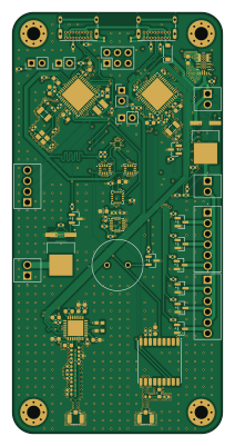
IRIS is an open source STM32 PCB design by teletype7, published on GitHub under the MIT license. It is a 4-layer board measuring 50 × 100 mm, with 160 components from 66 distinct parts.
Its main chip is the STM32U585CIUXQ, from the STM32 family. Other key parts include the MPM3610GQV-Z, IRFR9014PBF, ICM-42670-P, MMC5983MA and AT25SF041B-SSHB-B. By type, the board carries 59 capacitors, 45 resistors, 12 ICs, 12 inductors, 9 transistors and 5 connectors.
It belongs with the rf & radio and sensors designs in this gallery.
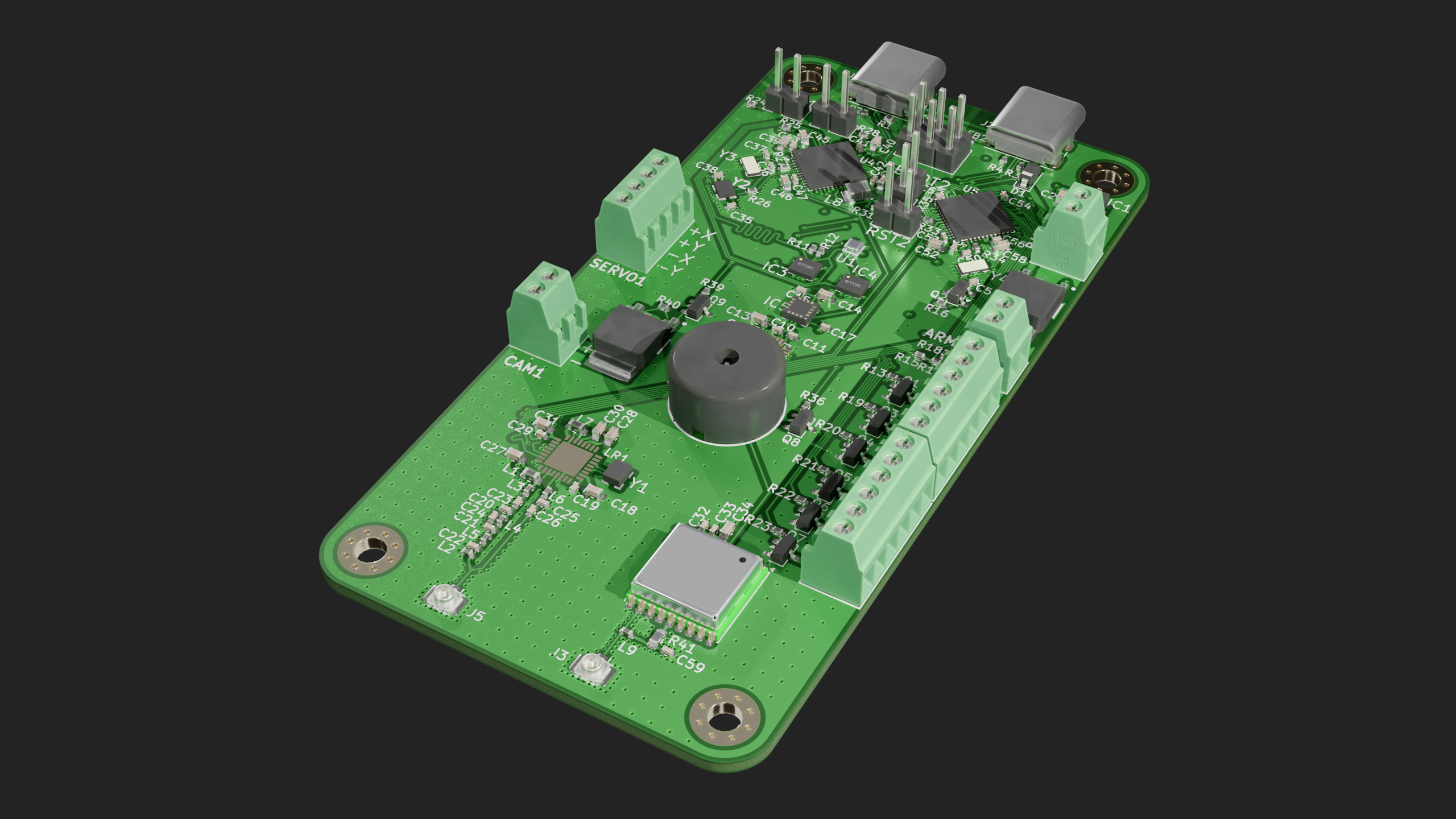
Main components on the IRIS
IRIS bill of materials (BOM)
160 components, 66 distinct parts — part numbers from the project's BOM.
| Qty | Part | Footprint | Refs |
|---|---|---|---|
| 1 | MPM3610GQV-Z | MPM3606GQVZ | IC1 |
| 2 | IRFR9014PBF | TO228P990X238-3N | IC2, IC7 |
| 2 | ICM-42670-P ICM-45686 | ICM42670P | IC3, IC4 |
| 1 | MMC5983MA | MMC5983MA | IC5 |
| 1 | AT25SF041B-SSHB-B | SOIC127P600X175-8N | IC6 |
| 1 | BMP581 | BMP581 | U1 |
| 1 | H3LIS331DLTR | QFN300X300X100-16N | U2 |
| 1 | MAX-M10S | ublox_MAX | U3 |
| 1 | STM32U585CIUXQ STM32U585CIUxQ | QFN-48-1EP_7x7mm_P0.5mm_EP5.6x5.6mm | U4 |
| 1 | STM32U073CCUX STM32U073CCUx | QFN-48-1EP_7x7mm_P0.5mm_EP5.6x5.6mm | U5 |
| 6 | DMN3404L | SOT-23 | Q1, Q3, Q4, Q5, Q6, Q7 |
| 3 | MMBT2222A | SOT-23 | Q2, Q8, Q9 |
| 1 | ECS-TXO-25CSMV-320-AM-TR | ECSTXO25CSMV320AMTR | Y1 |
| 1 | ECS-160-8-36B2-CKM-TR | ECS160836B2CKMTR | Y2 |
| 2 | CM7V-T1A-32.768KHZ-9PF-10PPM-TA-QC CM7V-T1A-32.768KHZ | CM7V32768TBQA020 | Y3, Y4 |
| 2 | USB_C_RECEPTACLE_USB2.0_16P USB_C_Receptacle_USB2.0_16P | USB_C_Receptacle_GCT_USB4085 | J1, J2 |
| 2 | Conn_Coaxial | U.FL_Hirose_U.FL-R-SMT-1_Vertical | J3, J5 |
| 1 | MICRO_SD_CARD_DET2 Micro_SD_Card_Det2 | microSD_HC_Molex_104031-0811 | J10 |
| 1 | Arm | TBC05021GG | ARM1 |
| 1 | battery | TBC05021GG | BAT1 |
Show 46 more
| Qty | Part | Footprint | Refs |
|---|---|---|---|
| 4 | CONN_01X02 Conn_01x02 | PinHeader_1x02_P2.54mm_Vertical | BOOT1, BOOT2, RST1, RST2 |
| 1 | SCREW_TERMINAL_01X02 Screw_Terminal_01x02 | TBC05021GG | CAM1 |
| 1 | CONN_02X03_TOP_BOTTOM Conn_02x03_Top_Bottom | PinHeader_2x03_P2.54mm_Vertical | DEBUG1 |
| 1 | ~ | LR2021 | LR1 |
| 1 | PS1240P02BT | PS1240P02BT | LS1 |
| 2 | SCREW_TERMINAL_01X06 Screw_Terminal_01x06 | TBC05061GG | PYRO1, PYRO2 |
| 1 | CONN_01X04 Conn_01x04 | TBC05041GG | SERVO1 |
| 1 | D_Schottky | D_SOD-123 | D1 |
| 3 | BLM15AX102SN1D | NFZ15SG152SN10B | FB1, FB2, FB3 |
| 1 | 12NH 12nH | L_0603_1608Metric | L1 |
| 1 | 22NH 22nH | L_0402_1005Metric | L2 |
| 1 | 4.7NH 4.7nH | L_0402_1005Metric | L3 |
| 1 | 3.9NH 3.9nH | L_0402_1005Metric | L4 |
| 1 | 7.5NH 7.5nH | L_0402_1005Metric | L5 |
| 1 | 24NH 24nH | L_0402_1005Metric | L6 |
| 1 | 2.2UH 2.2uH | L_0603_1608Metric | L7 |
| 1 | 2.2 uH, 1.5A | INDC2520X120N | L8 |
| 1 | 27NH 27nH | L_0402_1005Metric | L9 |
| 2 | 22UF 22uF | C_0603_1608Metric | C1, C2 |
| 7 | 10UF 10uF | C_0603_1608Metric | C3, C13, C16, C34, C40, C48, C52 |
| 24 | 100NF 100nF | C_0402_1005Metric | C4, C5, C6, C7, C8, C9, C10, C11 +16 |
| 6 | 1UF 1uF | C_0603_1608Metric | C14, C27, C28, C39, C46, C58 |
| 4 | 2.2UF 2.2uF | C_0603_1608Metric | C18, C30, C44, C45 |
| 1 | 47PF 47pF | C_0402_1005Metric | C19 |
| 1 | 7.5PF 7.5pF | C_0402_1005Metric | C20 |
| 1 | 3.9PF 3.9pF | C_0402_1005Metric | C21 |
| 2 | 1.8PF 1.8pF | C_0402_1005Metric | C22, C24 |
| 1 | 22PF 22pF | C_0402_1005Metric | C23 |
| 1 | 2.2PF 2.2pF | C_0402_1005Metric | C25 |
| 1 | 18PF 18pF | C_0402_1005Metric | C26 |
| 1 | 4.7UF 4.7uF | C_0603_1608Metric | C31 |
| 2 | 8PF 8pF | C_0402_1005Metric | C35, C38 |
| 4 | 9PF 9pF | C_0402_1005Metric | C36, C37, C50, C51 |
| 1 | 10NF 10nF | C_0402_1005Metric | C59 |
| 4 | 5.1K | R_0402_1005Metric | R1, R2, R3, R4 |
| 1 | 75K 75k | R_0402_1005Metric | R5 |
| 1 | 24K 24k | R_0402_1005Metric | R6 |
| 1 | 39K 39k | R_0402_1005Metric | R7 |
| 2 | 100K 100k | R_0402_1005Metric | R8, R18 |
| 4 | 2.7K 2.7k | R_0402_1005Metric | R9, R10, R11, R12 |
| 12 | 1k | R_0402_1005Metric | R13, R16, R19, R20, R21, R22, R23, R26 +4 |
| 2 | 12K 12k | R_0402_1005Metric | R14, R29 |
| 2 | 3k | R_0402_1005Metric | R15, R30 |
| 14 | 10K 10k | R_0402_1005Metric | R17, R24, R25, R28, R31, R33, R35, R37 +6 |
| 1 | 10K 100k | R_0402_1005Metric | R32 |
| 1 | 10 | R_0603_1608Metric | R41 |
IRIS design files
The KiCad project lives in the teletype7/IRIS repository on GitHub; these links point at the commit this page was built from.
IRIS: common questions
What microcontroller does the IRIS use?
The IRIS is built around the STM32U585CIUXQ, from the STM32 family.
How big is the IRIS PCB?
The IRIS measures 50 × 100 mm, has 4 copper layers and is 1.6 mm thick.
How many components are on the IRIS?
160 components, from 66 distinct parts, with part numbers taken from the project's own BOM. The full bill of materials is listed on this page.
Where can I download the IRIS design files?
From the teletype7/IRIS repository on GitHub, which has the KiCad layout, the schematic and the BOM; the links under Design files point to each one.
Can I use the IRIS design in my own project?
Yes, under the terms of its MIT license, which teletype7 chose for the repository.
Can I test firmware for the IRIS without the hardware?
Yes. HardLabs builds a simulation of the board from its netlist and BOM, so you can run and debug STM32 firmware against it before you order a PCB.
Similar boards
 STM32
STM32LumenPnP Motherboard
opulo-inc
149 × 95 mm296 parts4LCC-BY-SA-4.03.7k STM32
STM32Type c
google
188 × 30 mm17 parts2LApache-2.02.9k STM32
STM32Main panel
234 × 84 mm26 parts4LApache-2.02.9k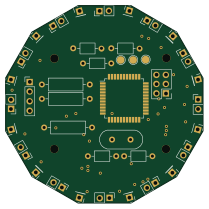 STM32
STM32Base
52.3 × 52.3 mm36 parts2LApache-2.02.9k STM32
STM32Type a
150 × 30 mm14 parts2LApache-2.02.9k STM32
STM32Type e
140.5 × 30 mm13 parts2LApache-2.02.9k