
ZigbeeRetrofit

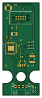
About the ZigbeeRetrofit PCB
ZigbeeRetrofit is an open source PCB design by tfindlay-au, published on GitHub. It is a 2-layer board measuring 20 × 50 mm, with 24 components from 18 distinct parts.
Other key parts include the CC2531F256RHAT and SPX3819M5-L-3-3. By type, the board carries 12 capacitors, 3 connectors, 2 ICs, 2 crystals, 2 inductors and 2 resistors.
It belongs with the iot & wireless and retro computing designs in this gallery.
From the project
Project to retrofit a board into M5Stack case
Designed in KiCad 6.0.9 The output board measures 50mm x 20mm and contains cutouts for mounting in the case /w lego fittings
The design incorporates a Tag-Connect 10 pad pogo pin (TC-2050-NL) footprint to write/flash firmware. The design also incorporates a 4-pin Grove connector with UART interface for easy connection with M5Stack Atom products.
The design also uses the following symbols: - 110990037: Seed Studio Grove connector - CC2531F256RHAT: TI Chip Zigbee chip - TC2050-IDC-NL: 10 pin flash connection - U.FL-R-SMT-1_10: UFL antenna connector - ECS-320-13-42-CKM-TR: 32 Mhz Crystal -…
Main components on the ZigbeeRetrofit
ZigbeeRetrofit bill of materials (BOM)
24 components, 18 distinct parts.
| Qty | Part | Footprint | Refs |
|---|---|---|---|
| 1 | CC2531F256RHAT | QFN50P600X600X100-41N | U1 |
| 1 | SPX3819M5-L-3-3 | SOT-23-5 | U2 |
| 1 | 32 Mhz | XTAL_ECS-320-13-42-CKM-TR | Y1 |
| 1 | ECS-.327-12.5-34RR-TR | XTAL_ECS-.327-12.5-34RR-TR | Y2 |
| 1 | 110990037 | JST_PH_S4B-PH-K_1x04_P2.00mm_Horizontal | J1 |
| 1 | U.FL-R-SMT-1(10) | HRS_U.FL-R-SMT-1(10) | J2 |
| 1 | TC2050-IDC-NL | TAG-CONNECT_TC2050-IDC-NL | J3 |
| 1 | LTST-C281KGKT | 0402(POL) | D1 |
| 2 | 2nH | INDC1006X60N | L1, L2 |
| 1 | 2.2pF | C_0402_1005Metric | C1 |
| 2 | 1pF | C_0402_1005Metric | C2, C3 |
| 2 | 27pF | C_0402_1005Metric | C4, C7 |
| 2 | 18pF | C_0402_1005Metric | C5, C6 |
| 1 | 1uF | C_0402_1005Metric | C8 |
| 2 | 22uF | C_0402_1005Metric | C9, C10 |
| 2 | 15pF | C_0402_1005Metric | C11, C12 |
| 1 | 56K Ohm | RES_ERJ-2GEJ563X | R1 |
| 1 | 150 Ohm | RES_ERJ-2GEJ151X | R2 |
ZigbeeRetrofit design files
The KiCad project lives in the tfindlay-au/ZigbeeRetrofit repository on GitHub; these links point at the commit this page was built from.
- LayoutZigbeeRetrofit.kicad_pcb
- SchematicZigbeeRetrofit.kicad_sch
ZigbeeRetrofit: common questions
How big is the ZigbeeRetrofit PCB?
The ZigbeeRetrofit measures 20 × 50 mm, has 2 copper layers and is 1.6 mm thick.
How many components are on the ZigbeeRetrofit?
24 components, from 18 distinct parts. The full bill of materials is listed on this page.
Where can I download the ZigbeeRetrofit design files?
From the tfindlay-au/ZigbeeRetrofit repository on GitHub, which has the KiCad layout and the schematic; the links under Design files point to each one.
Can I use the ZigbeeRetrofit design in my own project?
The repository has no license, so all rights stay with tfindlay-au. Use it as a reference, and ask the author before reusing the design.
Similar boards

EinkPDA screen
TalismanDesign
95 × 54 mm27 parts2LApache-2.02.0k
Expansion Card Retrofit
FrameworkComputer
24 × 27.3 mm5 parts2LCC-BY-4.01.1k
Rgb to hdmi
hoglet67
77 × 97 mm67 parts2LGPL-3.01.0k
Buffer
53.9 × 23.2 mm13 parts2LGPL-3.01.0k
Amiga External
21.9 × 76.7 mm6 parts2LGPL-3.01.0k
X1
121.9 × 81.3 mm51 parts2LGPL-3.01.0k