
Power-Supply-Unit

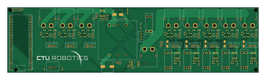
About the Power-Supply-Unit PCB
Power-Supply-Unit is an open source RP2040/RP2350 PCB design by Thoric16, published on GitHub. It is a 4-layer board measuring 230 × 60 mm, with 152 components from 29 distinct parts.
Its main chip is the RaspberryPi_Pico, from the RP2040/RP2350 family. Other key parts include the ADS7828 and ACS712xLCTR-30A. By type, the board carries 58 resistors, 24 transistors, 21 connectors, 19 capacitors, 13 diodes and 7 ICs.
It belongs with the power & battery and robotics & motion designs in this gallery.
From the project
A custom-designed robotics Power Supply Unit (PSU) featuring multi-rail buck regulation, remotely switchable outputs, current monitoring, and a hardware E-Stop loop.
A custom-designed, high-reliability Power Supply Unit (PSU) engineered to act as the centralized power management hub and hardware safety backbone for an advanced robotics platform. This board safely bridges high-draw actuator systems with sensitive compute electronics, featuring real-time telemetry and integrated fault protection.
Centralized Voltage Regulation: Features onboard step-down (buck) converters engineered to deliver clean, highly stable regulated voltage rails dedicated to sensitive compute units and sensor payloads. Dynamic Power Routing: Implements remotely switchable outputs…
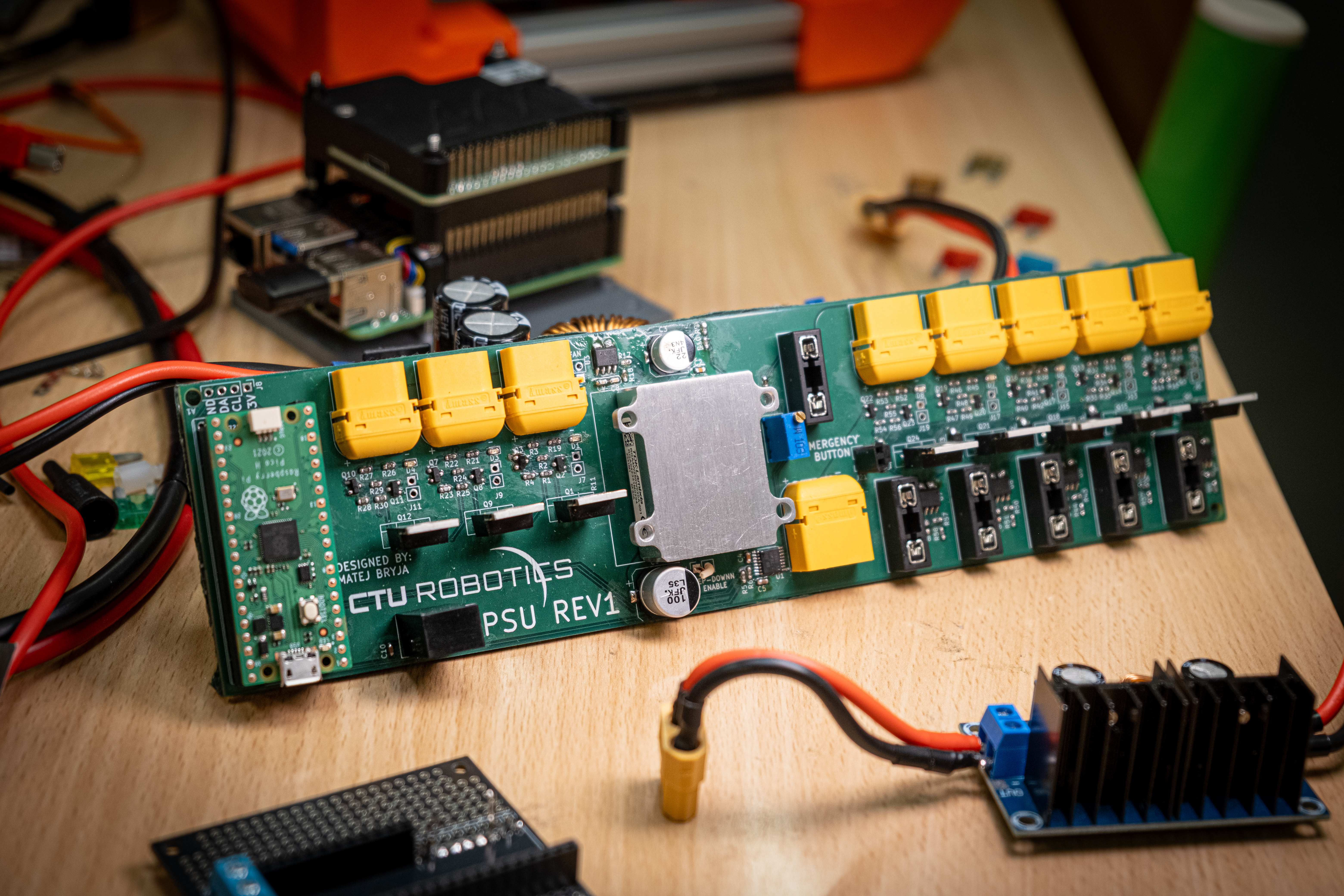
Main components on the Power-Supply-Unit
Power-Supply-Unit bill of materials (BOM)
152 components, 29 distinct parts.
| Qty | Part | Footprint | Refs |
|---|---|---|---|
| 1 | ADS7828 | TSSOP-16_4.4x5mm_P0.65mm | U1 |
| 6 | ACS712xLCTR-30A | SOIC-8_3.9x4.9mm_P1.27mm | U2, U3, U4, U5, U6, U7 |
| 1 | RaspberryPi_Pico | RaspberryPi_Pico_Common_THT | A1 |
| 8 | IRLZ44 | TO-220-3_Vertical_custom | Q1, Q6, Q9, Q12, Q15, Q18, Q21, Q24 |
| 16 | MMBT2222A | SOT-23 | Q2, Q3, Q4, Q5, Q7, Q8, Q10, Q11 +8 |
| 8 | XT60PW-F | AMASS_XT60PW-F_1x02_P7.20mm_Horizontal | J1, J3, J10, J12, J14, J16, J18, J20 |
| 10 | Conn_01x02_Pin | PinSocket_1x02_P2.54mm_Vertical | J2, J6, J7, J9, J11, J13, J15, J17 +2 |
| 1 | XT60PW-M | AMASS_XT60PW-M_1x02_P7.20mm_Horizontal | J4 |
| 1 | FAN | PinSocket_1x02_P2.54mm_Vertical | J5 |
| 1 | Conn_01x04_Pin | PinHeader_1x04_P2.54mm_Vertical | J8 |
| 6 | 01000066Z | 01000066Z | F1, F2, F3, F4, F5, F6 |
| 1 | RGA4W250W020A-001 | RGA4W250W020A001 | PS1 |
| 1 | RBT20W24S05 | RBT20W24S05 | PS2 |
| 1 | R_Potentiometer_Trim | Potentiometer_Bourns_3296W_Vertical | RV1 |
| 8 | LED | LED_0603_1608Metric | D1, D2, D3, D4, D5, D6, D7, D8 |
| 5 | US1M | D_SMA | D10, D11, D12, D13, D14 |
| 1 | 100u | CP_Elec_10x10.5 | C1 |
| 7 | 0.1u | C_0603_1608Metric | C2, C6, C8, C12, C14, C16, C18 |
| 1 | 22u | CP_Elec_8x6.2 | C3 |
| 1 | 100n | C_0603_1608Metric | C4 |
Show 9 more
| Qty | Part | Footprint | Refs |
|---|---|---|---|
| 1 | 10u | C_0603_1608Metric | C5 |
| 6 | 1n | C_0603_1608Metric | C7, C9, C13, C15, C17, C19 |
| 2 | 4.7u | C_0603_1608Metric | C10, C11 |
| 30 | 10k | R_0603_1608Metric | R1, R4, R7, R8, R10, R11, R14, R16 +22 |
| 16 | 1k | R_0603_1608Metric | R2, R3, R13, R15, R22, R24, R27, R29 +8 |
| 2 | 2k | R_0603_1608Metric | R5, R6 |
| 1 | 47k | R_0603_1608Metric | R9 |
| 1 | 220k | R_0603_1608Metric | R12 |
| 8 | ? | R_0603_1608Metric | R19, R20, R21, R26, R31, R38, R45, R52 |
Power-Supply-Unit design files
The KiCad project lives in the Thoric16/Power-Supply-Unit repository on GitHub; these links point at the commit this page was built from.
- Layouthardware/PSU.kicad_pcb
- Schematichardware/PSU.kicad_sch
Power-Supply-Unit: common questions
What microcontroller does the Power-Supply-Unit use?
The Power-Supply-Unit is built around the RaspberryPi_Pico, from the RP2040/RP2350 family.
How big is the Power-Supply-Unit PCB?
The Power-Supply-Unit measures 230 × 60 mm, has 4 copper layers and is 1.6 mm thick.
How many components are on the Power-Supply-Unit?
152 components, from 29 distinct parts. The full bill of materials is listed on this page.
Where can I download the Power-Supply-Unit design files?
From the Thoric16/Power-Supply-Unit repository on GitHub, which has the KiCad layout and the schematic; the links under Design files point to each one.
Can I use the Power-Supply-Unit design in my own project?
The repository has no license, so all rights stay with Thoric16. Use it as a reference, and ask the author before reusing the design.
Can I test firmware for the Power-Supply-Unit without the hardware?
Yes. HardLabs builds a simulation of the board from its netlist and BOM, so you can run and debug RP2040/RP2350 firmware against it before you order a PCB.
Similar boards
 RP2040/RP2350
Open Book Abridged Edition
joeycastillo
85 × 115 mm29 parts2LCC-BY-SA-4.08.1k RP2040/RP2350
Corne
foostan
277.2 × 107.5 mm164 parts2LCC-BY-4.07.7k RP2040/RP2350
Corne
277.2 × 107.5 mm164 parts2LCC-BY-4.07.7k RP2040/RP2350
LogicAnalyzer
gusmanb
57 × 55.2 mm6 parts2LGPL-3.05.0k RP2040/RP2350
Jitx design
55.5 × 65 mm26 parts4LGPL-3.05.0k RP2040/RP2350
Pro V2
kata0510
290.1 × 130 mm270 parts2LMIT2.3k