
Audio-1-Labo-Opstelling

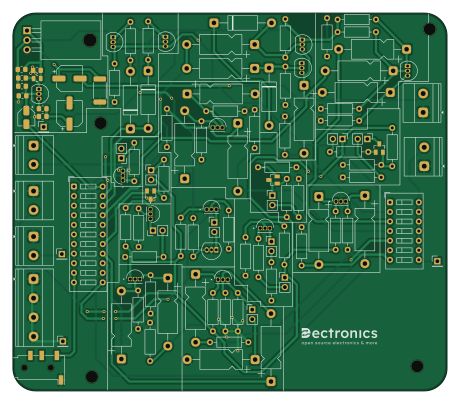
About the Audio-1-Labo-Opstelling PCB
Audio-1-Labo-Opstelling is an open source PCB design by TiebeDeclercq, published on GitHub. It is a 2-layer board measuring 114.9 × 100 mm, with 118 components from 45 distinct parts.
By type, the board carries 52 resistors, 20 capacitors, 19 transistors, 11 connectors, 10 jumpers and 4 diodes.
It belongs with the audio designs in this gallery.
From the project
Complete audio versterker PCB voor labo-opdrachten met Klasse A, AB en push-pull configuraties plus frequentie-analyse circuits. En ook alles voor vermogenelektronica.
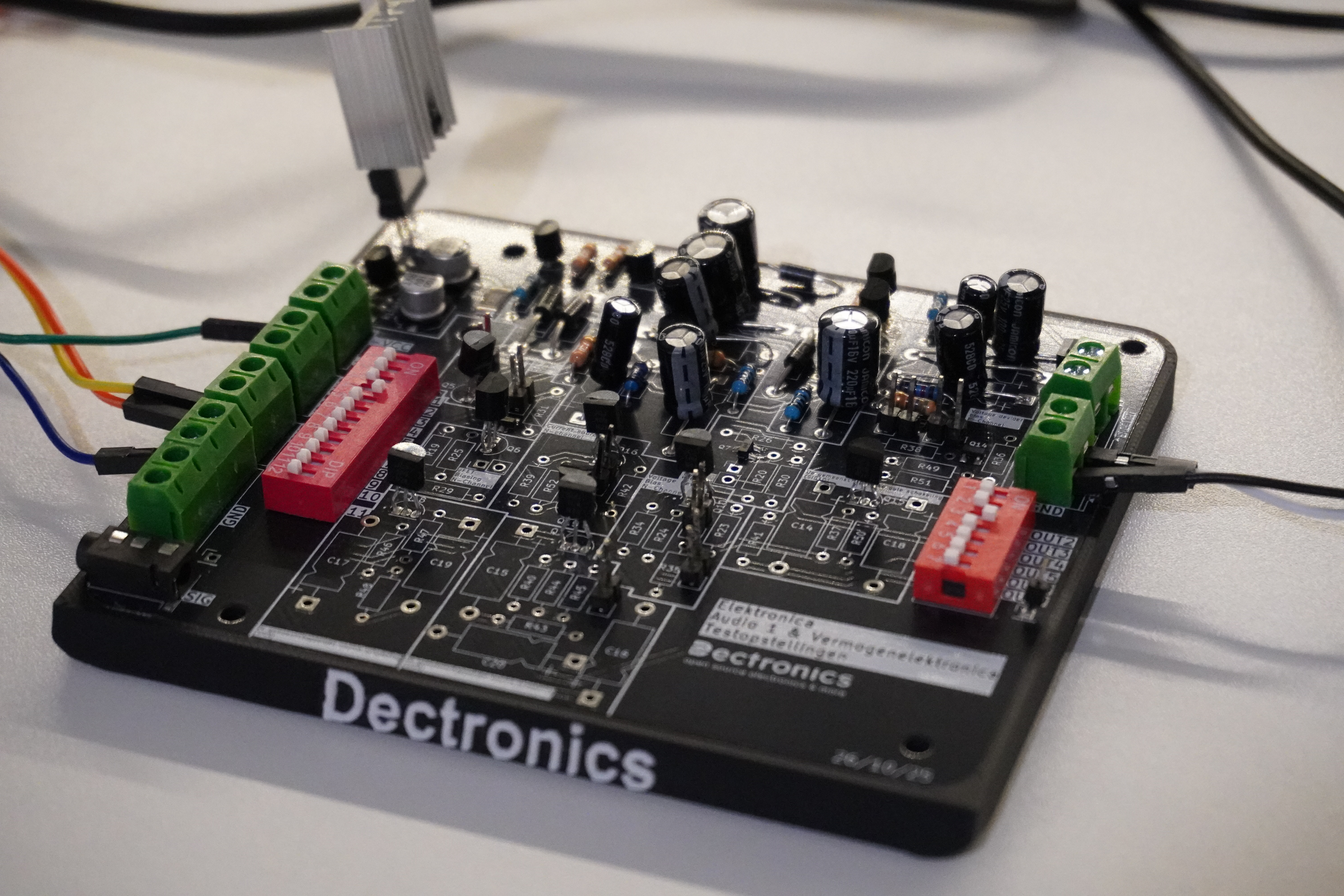
Complete printplaat met alle schakelingen voor audio 1 en vermogenelektronica @Vives kortrijk. Met een printbare voet voor betere stabiliteit en geen kortsluiting te krijgen. Op deze voet wordt er gewerkt met heated inserts (M3) voor het monteren van de print.
De printplaat bevat een Klasse A versterker in twee-traps configuratie met Darlington uitgang. Daarnaast is er een Klasse AB versterker met push-pull configuratie en diode bias die werkt op dual supply spanning. Voor frequentie-analyse zijn er twee circuits: een BJT common emitter configuratie en een JFET common source configuratie…
Audio-1-Labo-Opstelling bill of materials (BOM)
118 components, 45 distinct parts — part numbers from the project's BOM.
| Qty | Part | Footprint | Refs |
|---|---|---|---|
| 5 | BC547 | TO-92_Inline | Q1, Q3, Q8, Q9, Q19 |
| 1 | TIP142 | TO-220-3_Horizontal_TabDown | Q2 |
| 8 | NJFET | TRANS_J109 | Q4, Q5, Q6, Q10, Q15, Q16, Q17, Q18 |
| 3 | PJFET | SOT23 | Q7, Q13, Q14 |
| 2 | BC557 | TO-92_Inline | Q11, Q12 |
| 1 | AUDIOJACK2_SWITCH AudioJack2_Switch | Jack_3.5mm_KoreanHropartsElec_PJ-320D-4A_Horizontal | J1 |
| 4 | CONN_01X01_PIN Conn_01x01_Pin | PinHeader_1x01_P2.54mm_Vertical | J2, J3, J7, J9 |
| 1 | Speaker 8 Ohm | TerminalBlock_Phoenix_MKDS-1,5-2_1x02_P5.00mm_Horizontal | J4 |
| 1 | GDN terminals | TerminalBlock_Phoenix_MKDS-1,5-4-5.08_1x04_P5.08mm_Horizontal | J5 |
| 1 | Sig | TerminalBlock_Phoenix_MKDS-1,5-2_1x02_P5.00mm_Horizontal | J6 |
| 1 | Out | TerminalBlock_Phoenix_MKDS-1,5-2_1x02_P5.00mm_Horizontal | J8 |
| 2 | Power in | TerminalBlock_Phoenix_MKDS-1,5-2_1x02_P5.00mm_Horizontal | J10, J11 |
| 7 | JUMPER_2_OPEN Jumper_2_Open | PinHeader_1x02_P2.54mm_Vertical | JP1, JP3, JP4, JP6, JP7, JP8, JP10 |
| 2 | Jmpr | PinHeader_1x02_P2.54mm_Vertical | JP2, JP5 |
| 1 | ~ | PinHeader_1x02_P2.54mm_Vertical | JP9 |
| 1 | SW_DIP_X07 SW_DIP_x07 | SW_DIP_SPSTx07_Slide_9.78x19.96mm_W7.62mm_P2.54mm | SW1 |
| 1 | SW_DIP_X11 SW_DIP_x11 | SW_DIP_SPSTx11_Slide_9.78x30.12mm_W7.62mm_P2.54mm | SW2 |
| 4 | D | D_DO-15_P15.24mm_Horizontal | D1, D2, D3, D4 |
| 1 | 0.22UF 0.22uF | C_0805_2012Metric | C1 |
| 9 | ~ | CP_Axial_L11.0mm_D5.0mm_P18.00mm_Horizontal | C2, C3, C5, C6, C9, C10, C15, C16 +1 |
Show 25 more
| Qty | Part | Footprint | Refs |
|---|---|---|---|
| 1 | 1UF 1uF | CP_Elec_4x5.4 | C4 |
| 2 | 100UF 100uF | CP_Elec_6.3x5.4 | C7, C8 |
| 2 | 22UF 22uF | CP_Axial_L11.0mm_D5.0mm_P18.00mm_Horizontal | C11, C13 |
| 1 | 470 | CP_Axial_L11.0mm_D5.0mm_P18.00mm_Horizontal | C12 |
| 2 | C2 | CP_Axial_L11.0mm_D5.0mm_P18.00mm_Horizontal | C14, C19 |
| 2 | C1 | CP_Axial_L11.0mm_D5.0mm_P18.00mm_Horizontal | C17, C18 |
| 1 | 56K 56k | R_0805_2012Metric_Pad1.20x1.40mm_HandSolder | R1 |
| 1 | 4.7K 4.7k | R_0805_2012Metric_Pad1.20x1.40mm_HandSolder | R2 |
| 1 | 5.6K 5.6k | R_0805_2012Metric_Pad1.20x1.40mm_HandSolder | R3 |
| 1 | Rc | R_Axial_DIN0207_L6.3mm_D2.5mm_P10.16mm_Horizontal | R4 |
| 10 | Rd | R_Axial_DIN0207_L6.3mm_D2.5mm_P10.16mm_Horizontal | R5, R18, R19, R20, R24, R31, R37, R38 +2 |
| 6 | ~ | R_Axial_DIN0207_L6.3mm_D2.5mm_P10.16mm_Horizontal | R6, R11, R23, R34, R36, R49 |
| 5 | Rl | R_Axial_DIN0207_L6.3mm_D2.5mm_P10.16mm_Horizontal | R7, R8, R41, R43, R48 |
| 1 | 10K 10k | R_0805_2012Metric_Pad1.20x1.40mm_HandSolder | R9 |
| 1 | 68 | R_0805_2012Metric_Pad1.20x1.40mm_HandSolder | R10 |
| 6 | Rg | R_Axial_DIN0207_L6.3mm_D2.5mm_P10.16mm_Horizontal | R12, R25, R26, R42, R44, R46 |
| 1 | 22K 22k | R_0805_2012Metric_Pad1.20x1.40mm_HandSolder | R13 |
| 1 | 33, 2W | R_2512_6332Metric_Pad1.40x3.35mm_HandSolder | R14 |
| 1 | 560 | R_0805_2012Metric_Pad1.20x1.40mm_HandSolder | R15 |
| 2 | Re | R_Axial_DIN0207_L6.3mm_D2.5mm_P10.16mm_Horizontal | R16, R52 |
| 8 | Rs | R_Axial_DIN0207_L6.3mm_D2.5mm_P10.16mm_Horizontal | R17, R29, R30, R35, R45, R47, R50, R51 |
| 2 | 430 | R_Axial_DIN0207_L6.3mm_D2.5mm_P10.16mm_Horizontal | R21, R32 |
| 2 | 470 | R_Axial_DIN0207_L6.3mm_D2.5mm_P10.16mm_Horizontal | R22, R33 |
| 1 | 16 | R_Axial_DIN0207_L6.3mm_D2.5mm_P10.16mm_Horizontal | R27 |
| 1 | 50 | R_Axial_DIN0207_L6.3mm_D2.5mm_P10.16mm_Horizontal | R28 |
Audio-1-Labo-Opstelling design files
The KiCad project lives in the TiebeDeclercq/Audio-1-Labo-Opstelling repository on GitHub; these links point at the commit this page was built from.
Audio-1-Labo-Opstelling: common questions
How big is the Audio-1-Labo-Opstelling PCB?
The Audio-1-Labo-Opstelling measures 114.9 × 100 mm, has 2 copper layers and is 1.6 mm thick.
How many components are on the Audio-1-Labo-Opstelling?
118 components, from 45 distinct parts, with part numbers taken from the project's own BOM. The full bill of materials is listed on this page.
Where can I download the Audio-1-Labo-Opstelling design files?
From the TiebeDeclercq/Audio-1-Labo-Opstelling repository on GitHub, which has the KiCad layout, the schematic and the BOM; the links under Design files point to each one.
Can I use the Audio-1-Labo-Opstelling design in my own project?
The repository has no license, so all rights stay with TiebeDeclercq. Use it as a reference, and ask the author before reusing the design.
Similar boards
KLOR
GEIGEIGEIST
160.2 × 118.3 mm79 parts2LGPL-3.01.2k
ButtonsLEDs
shanteacontrols
390 × 37 mm82 parts2LApache-2.0956
USB
52 × 12.6 mm6 parts2LApache-2.0956
Pots
390 × 93 mm75 parts2LApache-2.0956
PicoGUS Hand386
polpo
29.2 × 75.2 mm43 parts4LGPL-2.0800
Snark barker
schlae
231.1 × 106.7 mm193 parts2LNo license687