
Video signal booster board

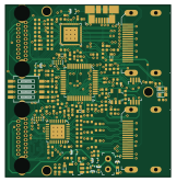
About the Video signal booster board
Video signal booster board is an open source Silicon Labs PCB design by timvideos, published on GitHub under the Apache-2.0 license. It is a 4-layer board measuring 40 × 41.5 mm, with 128 components from 31 distinct parts.
Its main chip is the EFM32HG322F64, from the Silicon Labs family. Other key parts include the INA180A1IDBVT, PTN3363, TPS2110APW, LP2985-33DBVR and NTS0102GT. By type, the board carries 61 resistors, 42 capacitors, 9 diodes, 8 ICs, 6 connectors and 1 switch.
From the project
This repository contains a KiCad PCB project for an open hardware board design that allows to improve the quality of HDMI video signals transmitted over long cables.
This repository contains a KiCad PCB project for an open hardware board design that allows to improve the quality of HDMI video signals transmitted over long cables.
HDMI signal preconditioning with a pair of PTN3363 HDMI level shifters. Signal equalization controlled with on-board DIP-Switch On-board SiLabs EFM32HG322F64 MCU for interactive control and board monitoring Supports different EDID connection scenarios
Main components on the Video signal booster board
Video signal booster board bill of materials (BOM)
128 components, 31 distinct parts — part numbers from the project's BOM.
| Qty | Part | Footprint | Refs |
|---|---|---|---|
| 1 | INA180A1IDBVT | SOT-23-5 | IC1 |
| 2 | PTN3363 | QFN-32-1EP_5x5mm | U1, U3 |
| 1 | TPS2110APW | TSSOP-8_W4.4mm | U2 |
| 1 | LP2985-33DBVR | SOT-753 | U4 |
| 2 | NTS0102GT | PSON50P100X195X50-8N | U5, U7 |
| 1 | EFM32HG322F64 | TQFP-48_7x7mm | U6 |
| 1 | 473460001 0473460001 | USB_Micro_B_Female_0473460001 | J1 |
| 2 | CHDMI-AMSS-01-C-VERTICAL CHDMI-AMSS-01-C-Vertical | CHDMI-AMSS-01-C-Vertical-mod1 | J2, J3 |
| 2 | 685119134923_ | HDMI_A_Female_685119134923 | J6, J9 |
| 1 | M20-9990246 | PinHeader_1x2_P2.54mm | J10 |
| 1 | TP_SMD_0_75MM | Testpoint_smd_0_75mm | 3V3 |
| 1 | 1571983-5 | 1571983-5 | SW1 |
| 7 | BAT54-02V-V-G | SOD-523 | D1, D2, D3, D4, D5, D6, D7 |
| 2 | LG_L29K-G2J1-24-Z | LED_0603 | D8, D9 |
| 2 | C_4U7_0603 C_4u7_0603 | 0603-cap | C1, C36 |
| 28 | C_100N_0402_6V3 C_100n_0402_6V3 | 0402-cap | C2, C3, C7, C8, C9, C10, C11, C12 +20 |
| 3 | C_10U_0603 C_10u_0603 | 0603-cap | C4, C17, C41 |
| 6 | C_1U_0402 C_1u_0402 | 0402-cap | C5, C6, C26, C34, C37, C42 |
| 2 | C_2U2_0402 C_2u2_0402 | 0402-cap | C28, C30 |
| 1 | C_10N_0402 C_10n_0402 | 0402-cap | C29 |
Show 11 more
| Qty | Part | Footprint | Refs |
|---|---|---|---|
| 2 | R_15R_0402 | 0402-res | R1, R2 |
| 16 | R_49R9_0402 | 0402-res | R3, R33, R42, R43, R44, R45, R46, R47 +8 |
| 4 | R_100R_0402 | 0402-res | R4, R16, R38, R41 |
| 7 | R_100K_0402 R_100k_0402 | 0402-res | R5, R6, R14, R15, R19, R24, R60 |
| 16 | R_10K_0402 R_10k_0402 | 0402-res | R9, R10, R21, R23, R26, R29, R31, R32 +8 |
| 2 | R_12K4_0402 R_12k4_0402 | 0402-res | R13, R17 |
| 7 | R_27K_0402 R_27k_0402 | 0402-res | R18, R20, R25, R27, R62, R64, R68 |
| 1 | R_806K_0402 R_806k_0402 | 0402-res | R30 |
| 1 | R_1R_0402 | 0402-res | R56 |
| 3 | R_4K7_0402 R_4k7_0402 | 0402-res | R63, R65, R69 |
| 2 | R_330R_0402 | 0402-res | R66, R67 |
Video signal booster board design files
The KiCad project lives in the timvideos/video-signal-booster-board repository on GitHub; these links point at the commit this page was built from.
Video signal booster board: common questions
What microcontroller does the Video signal booster board use?
The Video signal booster board is built around the EFM32HG322F64, from the Silicon Labs family.
How big is the Video signal booster board?
The Video signal booster board measures 40 × 41.5 mm, has 4 copper layers and is 1.55 mm thick.
How many components are on the Video signal booster board?
128 components, from 31 distinct parts, with part numbers taken from the project's own BOM. The full bill of materials is listed on this page.
Where can I download the Video signal booster board design files?
From the timvideos/video-signal-booster-board repository on GitHub, which has the KiCad layout and the BOM; the links under Design files point to each one.
Can I use the Video signal booster board design in my own project?
Yes, under the terms of its Apache-2.0 license, which timvideos chose for the repository.
Can I test firmware for the Video signal booster board without the hardware?
Yes. HardLabs builds a simulation of the board from its netlist and BOM, so you can run and debug Silicon Labs firmware against it before you order a PCB.
Similar boards
 Silicon Labs
Tomu hardware
im-tomu
13 × 9.4 mm11 parts2LCC-BY-SA-4.0365 Silicon Labs
One key
ahtn
14.5 × 14.5 mm10 parts2LNo license96 Silicon Labs
2key
36.5 × 17.5 mm7 parts2LNo license96 Silicon Labs
Ble soil moisture sensor
Miceuz
170 × 18 mm33 parts2LApache-2.033 Silicon Labs
Ble soil moisture sensor pannel
170 × 36 mm29 parts2LApache-2.033 Silicon Labs
Ym2413 dev
andete
115 × 45 mm146 parts2LNo license25