
Peak-And hold-Driver

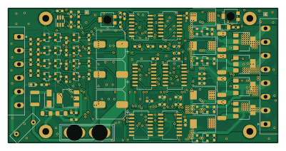
About the Peak-And hold-Driver PCB
Peak-And hold-Driver is an open source PCB design by Tjeerdie, published on GitHub under the GPL-3.0 license. It is a 2-layer board measuring 100.1 × 50 mm, with 112 components from 35 distinct parts.
Other key parts include the 74HC32, LM2901, 74HC74, LTC6992 and LM340. By type, the board carries 45 resistors, 20 transistors, 19 diodes, 14 capacitors, 8 ICs and 2 connectors.
From the project
Peak and hold injector driver for low-Z injectors.
I still do encourage everyone to use resistors if possible because the results are good and resistors have less components that can fail This design is specific to work with LPG injectors but could be used for any other low-Z injectors like TBI type and other high flow injectors. It could even be used for any coil type actuator like relays or valves
The board is designed in Kicad. So to see the schematic or to adjust the design to your liking open the Kicad project.
Main components on the Peak-And hold-Driver
Peak-And hold-Driver bill of materials (BOM)
112 components, 35 distinct parts — part numbers from the project's BOM.
| Qty | Part | Footprint | Refs |
|---|---|---|---|
| 1 | 74HC32 | SO-14_5.3x10.2mm_P1.27mm | U1 |
| 1 | LM2901 | SO-14_5.3x10.2mm_P1.27mm | U2 |
| 2 | 74HC74 | SO-14_5.3x10.2mm_P1.27mm | U3, U5 |
| 1 | LTC6992 | SOT-23-6_Handsoldering | U4 |
| 1 | LM340 | SOT-223-3_TabPin2 | U6 |
| 2 | 74HC08 | SO-14_5.3x10.2mm_P1.27mm | U7, U8 |
| 8 | 2N7002 | SOT-23 | Q1, Q2, Q3, Q4, Q9, Q10, Q11, Q12 |
| 8 | TSM2309 | SOT-23 | Q5, Q6, Q13, Q15, Q17, Q18, Q19, Q20 |
| 4 | C189606 IRLL 024N | SOT-223 | Q7, Q8, Q14, Q16 |
| 1 | RND 205-00203 | PhoenixContact_MSTBA_2,5_6-G-5,08_1x06_P5.08mm_Horizontal | J1 |
| 1 | RND 205-00205 | PhoenixContact_MSTBA_2,5_8-G-5,08_1x08_P5.08mm_Horizontal | J2 |
| 1 | Fuse | Fuse_Blade_ATO_directSolder | F1 |
| 1 | C70115 PPTC 16V2A | Fuse_1812_4532Metric_Pad1.30x3.40mm_HandSolder | F2 |
| 2 | 5K | Potentiometer_Bourns_3314R-1_Vertical_Hole | RV1, RV2 |
| 1 | 1N4007 | D_SMA | D2 |
| 1 | LL4148 | D_MiniMELF | D3 |
| 1 | C375446 BLUE | LED_0603_1608Metric_Pad1.05x0.95mm_HandSolder | D4 |
| 4 | BAT54S | SOT-23 | D5, D6, D13, D14 |
| 4 | BAV103 | D_MiniMELF | D7, D9, D15, D17 |
| 4 | BZX84C39 | D_SOT-23_ANK | D8, D10, D16, D18 |
Show 15 more
| Qty | Part | Footprint | Refs |
|---|---|---|---|
| 4 | SS36 | D_SMC | D11, D12, D19, D20 |
| 3 | 1MF 1mF | CP_Elec_10x12.5 | C1, C2, C3 |
| 2 | 10UF 10uf | C_1206_3216Metric_Pad1.42x1.75mm_HandSolder | C4, C7 |
| 9 | 220NF 220nf | C_0603_1608Metric_Pad1.05x0.95mm_HandSolder | C5, C6, C8, C9, C10, C11, C12, C13 +1 |
| 1 | VARISTOR-18V | RV_Disc_D12mm_W3.9mm_P7.5mm | R2 |
| 1 | 470K 470k | R_0603_1608Metric_Pad1.05x0.95mm_HandSolder | R3 |
| 1 | 100K 100k | R_0603_1608Metric_Pad1.05x0.95mm_HandSolder | R4 |
| 1 | 15K 15k | R_0603_1608Metric_Pad1.05x0.95mm_HandSolder | R5 |
| 14 | 470R | R_0603_1608Metric_Pad1.05x0.95mm_HandSolder | R6, R7, R9, R12, R15, R16, R17, R19 +6 |
| 8 | 10K | R_0603_1608Metric_Pad1.05x0.95mm_HandSolder | R8, R10, R11, R25, R28, R41, R43, R44 |
| 9 | 1K | R_0603_1608Metric_Pad1.05x0.95mm_HandSolder | R13, R14, R23, R24, R27, R30, R39, R40 +1 |
| 4 | 100R | R_0603_1608Metric_Pad1.05x0.95mm_HandSolder | R18, R20, R33, R36 |
| 4 | 0R1 | R_2512_6332Metric_Pad1.52x3.35mm_HandSolder | R21, R22, R37, R38 |
| 1 | 120K 120k | R_0603_1608Metric | R45 |
| 1 | 33K 33k | R_0603_1608Metric | R47 |
Peak-And hold-Driver design files
The KiCad project lives in the Tjeerdie/Peak-And-hold-Driver repository on GitHub; these links point at the commit this page was built from.
Peak-And hold-Driver: common questions
How big is the Peak-And hold-Driver PCB?
The Peak-And hold-Driver measures 100.1 × 50 mm, has 2 copper layers and is 1.6 mm thick.
How many components are on the Peak-And hold-Driver?
112 components, from 35 distinct parts, with part numbers taken from the project's own BOM. The full bill of materials is listed on this page.
Where can I download the Peak-And hold-Driver design files?
From the Tjeerdie/Peak-And-hold-Driver repository on GitHub, which has the KiCad layout and the BOM; the links under Design files point to each one.
Can I use the Peak-And hold-Driver design in my own project?
Yes, under the terms of its GPL-3.0 license, which Tjeerdie chose for the repository.