
Fanpico oled adapter

About the Fanpico oled adapter PCB
Fanpico oled adapter is an open source PCB design by tjko, published on GitHub under the GPL-3.0 license. It is a 2-layer board measuring 25 × 14.5 mm, with 3 components from 3 distinct parts.
It belongs with the displays & leds, iot & wireless and sensors designs in this gallery.
From the project
Fanpico: Open Source Programmable PWM (PC) Fan Controller
This is small adapter for making it easier to mount larger 1.5" 128x128 pixel OLED modules.
J1 is meant to be connected to FanPico J3 connector, then connecting OLED module to J2 (or J3).
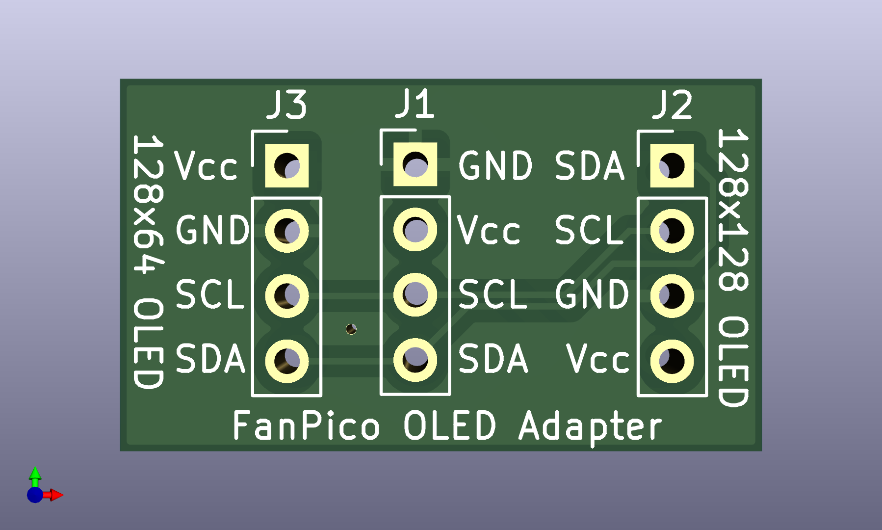
Fanpico oled adapter bill of materials (BOM)
3 components, 3 distinct parts — part numbers from the project's BOM.
| Qty | Part | Footprint | Refs |
|---|---|---|---|
| 1 | 171826-4 To_FanPico_J3 TE Connectivity | PinHeader_1x04_P2.54mm_Vertical | J1 |
| 1 | C2935975 1.5" OLED DEALON | PinHeader_1x04_P2.54mm_Vertical | J2 |
| 1 | C2935975 1.3" OLED (alt pinout) DEALON | PinHeader_1x04_P2.54mm_Vertical | J3 |
Fanpico oled adapter design files
The KiCad project lives in the tjko/fanpico repository on GitHub; these links point at the commit this page was built from.
Fanpico oled adapter: common questions
How big is the Fanpico oled adapter PCB?
The Fanpico oled adapter measures 25 × 14.5 mm, has 2 copper layers and is 1.6 mm thick.
How many components are on the Fanpico oled adapter?
3 components, from 3 distinct parts, with part numbers taken from the project's own BOM. The full bill of materials is listed on this page.
Where can I download the Fanpico oled adapter design files?
From the tjko/fanpico repository on GitHub, which has the KiCad layout, the schematic and the BOM; the links under Design files point to each one.
Can I use the Fanpico oled adapter design in my own project?
Yes, under the terms of its GPL-3.0 license, which tjko chose for the repository.
More boards in fanpico
Similar boards
BM28B0.6-24DSBreakout
scottbez1
15.2 × 35.6 mm3 parts2LApache-2.022.2k
LevelShifterBreakout
15.2 × 20.3 mm5 parts2LApache-2.022.2k
View base
81.2 × 81.2 mm81 parts2LApache-2.022.2k
View screen
35 × 35 mm12 parts2LApache-2.022.2k
Display eval
byrantech
52.1 × 22.6 mm12 parts4LMIT4.3k
ChainlinkBase
98.4 × 190.5 mm119 parts2LApache-2.04.2k