
Fanpico powerboard

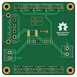
About the Fanpico powerboard PCB
Fanpico powerboard is an open source PCB design by tjko, published on GitHub under the GPL-3.0 license. It is a 2-layer board measuring 65 × 65 mm, with 15 components from 15 distinct parts.
By type, the board carries 11 connectors, 2 fuses, 1 diode and 1 resistor.
It belongs with the iot & wireless and sensors designs in this gallery.
From the project
Fanpico: Open Source Programmable PWM (PC) Fan Controller
This is a small power injector board for powering high-power fans, that require too much current to be connected directly into Fan ports on FanPico boards.
Board is meant to sit in between FanPico Fan ports and the high-power fans.
Fan Power Supply (12V) should be connected into one of the power inputs (only on input should be used at a time). Fans should be connected into "FAN" ports on the board, and cables connected from "FANCTRL" ports into FanPico (FAN ports) for fan control/monitoring.
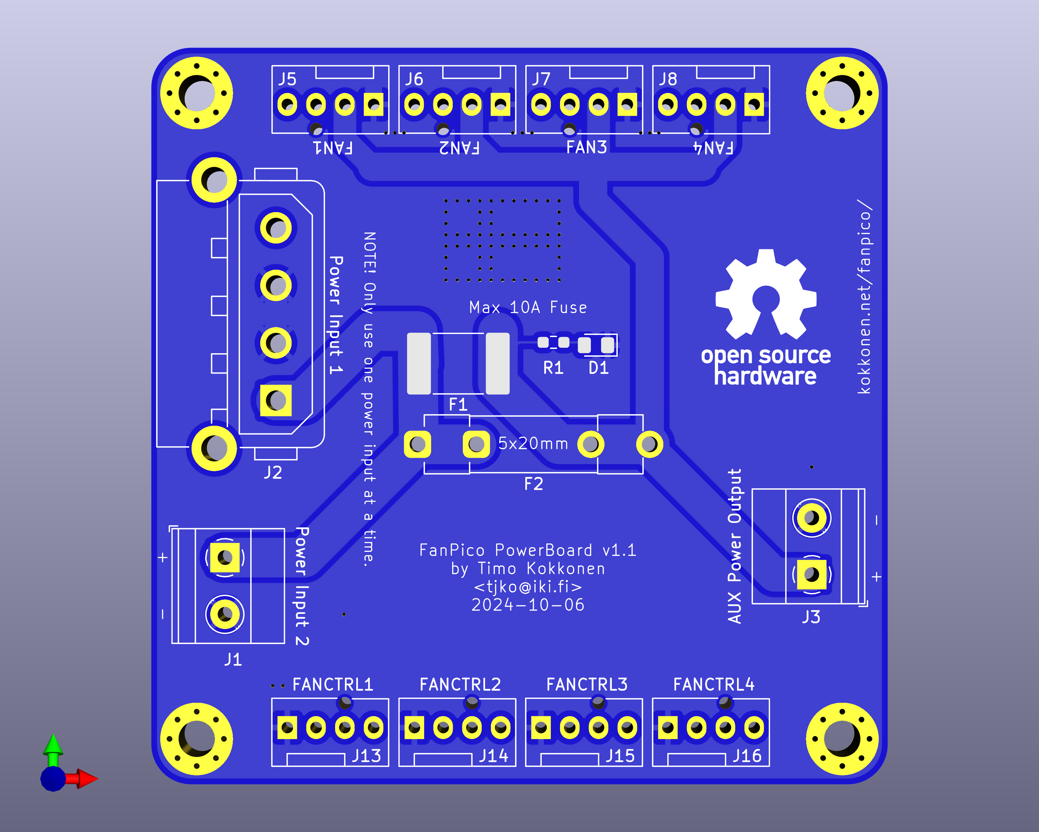
Fanpico powerboard bill of materials (BOM)
15 components, 15 distinct parts — part numbers from the project's BOM.
| Qty | Part | Footprint | Refs |
|---|---|---|---|
| 1 | 171826-4 Power Input 2 TE Connectivity | TerminalBlock_Phoenix_MKDS-1,5-2_1x02_P5.00mm_Horizontal | J1 |
| 1 | C2935975 Power Input 1 DEALON | TE_MATE-N-LOK_350211-1_1x04_P5.08mm_Vertical_and_RightAngle | J2 |
| 1 | C2935975 AUX Power Output DEALON | TerminalBlock_Phoenix_MKDS-1,5-2_1x02_P5.00mm_Horizontal | J3 |
| 1 | FAN1 | FanPinHeader_1x04_P2.54mm_Vertical | J5 |
| 1 | FAN2 | FanPinHeader_1x04_P2.54mm_Vertical | J6 |
| 1 | FAN3 | FanPinHeader_1x04_P2.54mm_Vertical | J7 |
| 1 | FAN4 | FanPinHeader_1x04_P2.54mm_Vertical | J8 |
| 1 | FANCTRL1 | FanPinHeader_1x04_P2.54mm_Vertical | J13 |
| 1 | FANCTRL2 | FanPinHeader_1x04_P2.54mm_Vertical | J14 |
| 1 | FANCTRL3 | FanPinHeader_1x04_P2.54mm_Vertical | J15 |
| 1 | XH-2AW FANCTRL4 BOOMELE(Boom Precision Elec) | FanPinHeader_1x04_P2.54mm_Vertical | J16 |
| 1 | C2977527 Polyfuse 10A BHFUSE | Fuse_2920_7451Metric_Pad2.10x5.45mm_HandSolder | F1 |
| 1 | C70072 10A TECHFUSE | Fuseholder_Clip-5x20mm_Littelfuse_445-030_Inline_P20.50x5.20mm_D1.30mm_Horizontal | F2 |
| 1 | SM5819PL-TP LED MCC | D_0805_2012Metric_Pad1.15x1.40mm_HandSolder | D1 |
| 1 | C22548 49.9K YAGEO | R_0603_1608Metric_Pad0.98x0.95mm_HandSolder | R1 |
Fanpico powerboard design files
The KiCad project lives in the tjko/fanpico repository on GitHub; these links point at the commit this page was built from.
Fanpico powerboard: common questions
How big is the Fanpico powerboard PCB?
The Fanpico powerboard measures 65 × 65 mm, has 2 copper layers and is 1.6 mm thick.
How many components are on the Fanpico powerboard?
15 components, from 15 distinct parts, with part numbers taken from the project's own BOM. The full bill of materials is listed on this page.
Where can I download the Fanpico powerboard design files?
From the tjko/fanpico repository on GitHub, which has the KiCad layout, the schematic and the BOM; the links under Design files point to each one.
Can I use the Fanpico powerboard design in my own project?
Yes, under the terms of its GPL-3.0 license, which tjko chose for the repository.
More boards in fanpico
Similar boards

Sensor smd
scottbez1
40 × 20 mm5 parts2LApache-2.04.2k
Sensors
StuckAtPrototype
15.2 × 9 mm14 parts4LApache-2.03.8k
EinkPDA screen
TalismanDesign
95 × 54 mm27 parts2LApache-2.02.0k
Microphone
Mentra-Community
5.5 × 6.1 mm6 parts2LMIT1.2k
TemperaturePCB PANEL
stuartpittaway
116 × 75.5 mm178 parts2LCC-BY-NC-4.01.1k
RPi RM0 WiFi/Bluetooth Module
schlae
11.1 × 14 mm76 parts6LNo license1.0k