
Fanpico

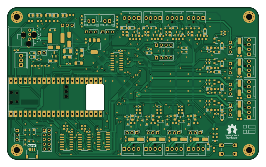
About the Fanpico PCB
Fanpico is an open source RP2040/RP2350 PCB design by tjko, published on GitHub under the GPL-3.0 license. It is a 2-layer board measuring 135 × 81.5 mm, with 208 components from 57 distinct parts.
Its main chip is the Pico, from the RP2040/RP2350 family. Other key parts include the C163728, C131932, C67402, C143326 and C9386. By type, the board carries 74 diodes, 59 resistors, 28 capacitors, 21 connectors, 12 jumpers and 7 ICs.
It belongs with the displays & leds, sensors and iot & wireless designs in this gallery.
From the project
Fanpico: Open Source Programmable PWM (PC) Fan Controller
v1.3 - Add QWIIC connector (to simplify connecting I2C sensors). - Add 1-Wire connector - Change J1 to a combination footprint (allows mounting either Floppy or DC connector). - Slightly improved ESD protection (TVS diodes added for most connectors)
v1.2c - Add support for using either SN74AHCT125 or SN74AHCT126 (as U1 and U2).
v1.2b - C5 was not derated correctly. Replace with 25V part for proper derating.
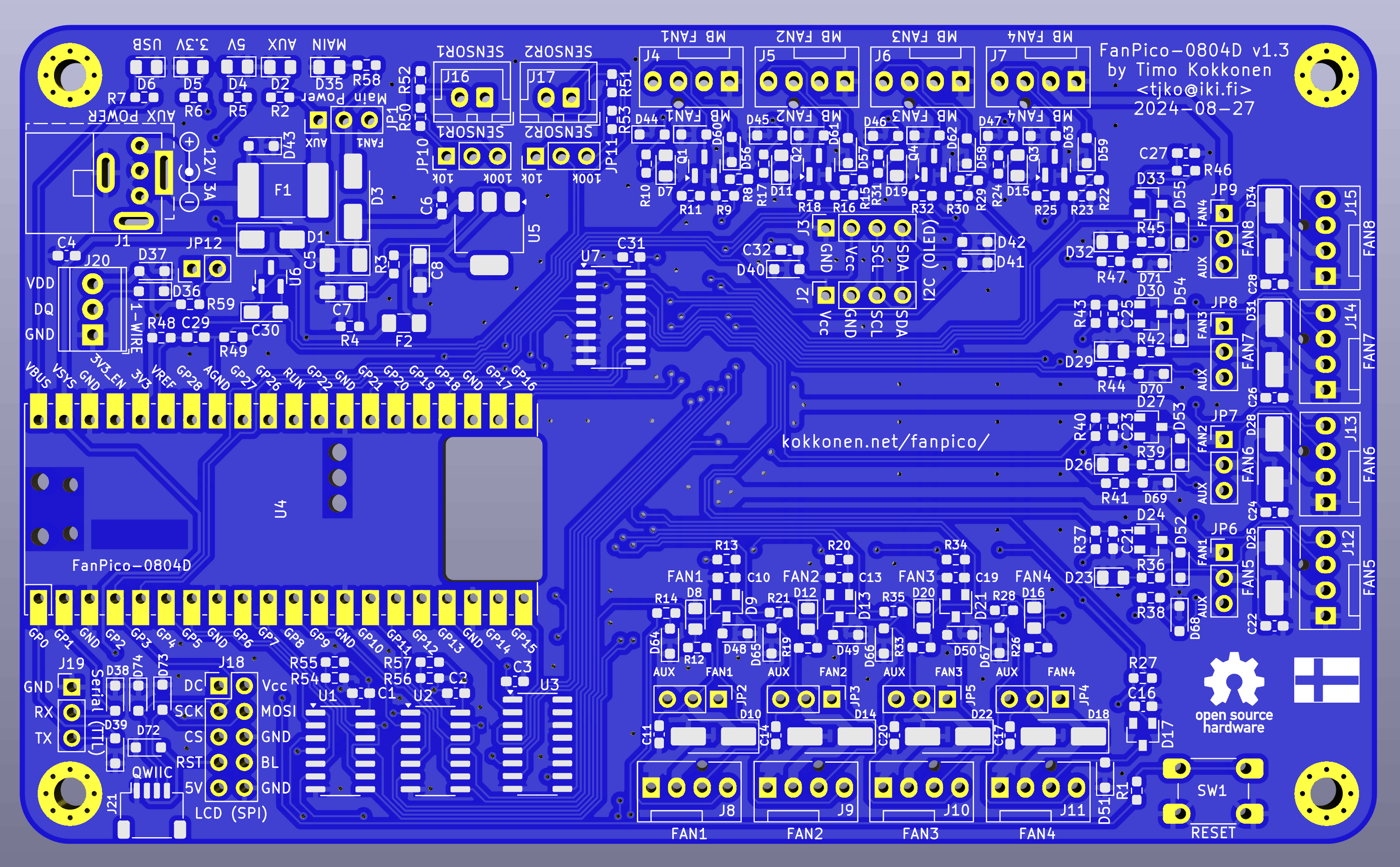
Main components on the Fanpico
Fanpico bill of materials (BOM)
208 components, 57 distinct parts — part numbers from the project's BOM.
| Qty | Part | Footprint | Refs |
|---|---|---|---|
| 2 | C163728 SN74AHCT126 TI | SOIC-14_3.9x8.7mm_P1.27mm | U1, U2 |
| 1 | C131932 CD74HC4050NSR TI | SOIC-16_3.9x9.9mm_P1.27mm | U3 |
| 1 | Pico Raspberry Pi | RPi_Pico_PicoW_SMD_TH | U4 |
| 1 | C67402 SPX1117-ADJ MaxLinear | SOT-223-3_TabPin2 | U5 |
| 1 | C143326 LM4040DBZ-3 Maxim | SOT-23 | U6 |
| 1 | C9386 74HC4051 Nexperia | SOIC-16_3.9x9.9mm_P1.27mm | U7 |
| 4 | C85047 2N7002K DIODES | SOT-23 | Q1, Q2, Q3, Q4 |
| 1 | 171826-4 Floppy / DC Connector TE Connectivity | TE 171826-4 Floppy 4-pin Combo | J1 |
| 1 | C2935975 I2C (OLED ALT) DEALON | PinSocket_1x04_P2.54mm_Vertical | J2 |
| 1 | C2935975 I2C (OLED) DEALON | PinSocket_1x04_P2.54mm_Vertical | J3 |
| 1 | MB Fan1 Input | FanPinHeader_1x04_P2.54mm_Vertical | J4 |
| 1 | MB Fan2 Input | FanPinHeader_1x04_P2.54mm_Vertical | J5 |
| 1 | MB Fan3 Input | FanPinHeader_1x04_P2.54mm_Vertical | J6 |
| 1 | MB Fan4 Input | FanPinHeader_1x04_P2.54mm_Vertical | J7 |
| 1 | Fan1 Output | FanPinHeader_1x04_P2.54mm_Vertical | J8 |
| 1 | Fan2 Output | FanPinHeader_1x04_P2.54mm_Vertical | J9 |
| 1 | Fan3 Output | FanPinHeader_1x04_P2.54mm_Vertical | J10 |
| 1 | Fan4 Output | FanPinHeader_1x04_P2.54mm_Vertical | J11 |
| 1 | Fan5 Output | FanPinHeader_1x04_P2.54mm_Vertical | J12 |
| 1 | Fan6 Output | FanPinHeader_1x04_P2.54mm_Vertical | J13 |
Show 37 more
| Qty | Part | Footprint | Refs |
|---|---|---|---|
| 1 | Fan7 Output | FanPinHeader_1x04_P2.54mm_Vertical | J14 |
| 1 | Fan8 Output | FanPinHeader_1x04_P2.54mm_Vertical | J15 |
| 1 | XH-2AW Sensor1 BOOMELE(Boom Precision Elec) | JST_XH_B2B-XH-A_1x02_P2.50mm_Vertical | J16 |
| 1 | XH-2AW Sensor2 BOOMELE(Boom Precision Elec) | JST_XH_B2B-XH-A_1x02_P2.50mm_Vertical | J17 |
| 1 | C492422 LCD (SPI) XFCN | PinHeader_2x05_P2.54mm_Vertical | J18 |
| 1 | C2937625 Serial Console (TTL) XFCN | PinHeader_1x03_P2.54mm_Vertical | J19 |
| 1 | 2.54-3P 1-Wire BOOMELE(Boom Precision Elec) | TerminalBlock_TE_282834-3_1x03_P2.54mm_Horizontal | J20 |
| 1 | C160404 QWIIC JST | JST_SH_SM04B-SRSS-TB_1x04-1MP_P1.00mm_Horizontal | J21 |
| 1 | C2977527 Polyfuse 3A BHFUSE | Fuse_2920_7451Metric_Pad2.10x5.45mm_HandSolder | F1 |
| 1 | C70072 Polyfuse 0.5A TECHFUSE | Fuse_1206_3216Metric_Pad1.42x1.75mm_HandSolder | F2 |
| 1 | C2937625 Power Selector XFCN | PinHeader_1x03_P2.54mm_Vertical | JP1 |
| 8 | C2937625 Fan Power XFCN | PinHeader_1x03_P2.54mm_Vertical | JP2, JP3, JP4, JP5, JP6, JP7, JP8, JP9 |
| 2 | C2937625 NTC Value XFCN | PinHeader_1x03_P2.54mm_Vertical | JP10, JP11 |
| 1 | C492401 1-Wire Pull-Up Enable XFCN | PinHeader_1x02_P2.54mm_Vertical | JP12 |
| 1 | C221880 SW_Push C&K | SW_PUSH_6mm_SMD_2 | SW1 |
| 1 | SM5819PL-TP SM5819PL 1A 40V MCC | D_SMA | D1 |
| 17 | C434432 LED 0805 (green) Yongyu Photoelectric | LED_0805_2012Metric_Pad1.15x1.40mm_HandSolder | D2, D4, D5, D6, D7, D8, D11, D12 +9 |
| 9 | C445494 ES1D 1A 200V MDD(Microdiode Semiconductor) | D_SMA_Handsoldering | D3, D10, D14, D18, D22, D25, D28, D31 +1 |
| 8 | C2844172 BAT54C FUXINSEMI | D_SOT-23_ANK | D9, D13, D17, D21, D24, D27, D30, D33 |
| 10 | C78439 3.3V TVS Brightking | D_SOD-323_HandSoldering | D36, D37, D38, D39, D40, D41, D42, D72 +2 |
| 17 | UDD32C12L01-ES 12V TVS ElecSuper | D_SOD-323_HandSoldering | D43, D44, D45, D46, D47, D48, D49, D50 +9 |
| 12 | C5180216 5V TVS ElecSuper | D_SOD-323_HandSoldering | D56, D57, D58, D59, D64, D65, D66, D67 +4 |
| 16 | C1591 0.1uF Samsung Electro-Mechanics | C_0603_1608Metric_Pad1.08x0.95mm_HandSolder | C1, C2, C3, C4, C6, C11, C14, C17 +8 |
| 1 | C7194 10uF 25V Kyocera AVX | CP_EIA-3528-12_Kemet-T_Pad1.50x2.35mm_HandSolder | C5 |
| 3 | C7171 10uF 16V Kyocera AVX | CP_EIA-3216-18_Kemet-A_Pad1.58x1.35mm_HandSolder | C7, C8, C30 |
| 8 | C1588 1nF Samsung Electro-Mechanics | C_0603_1608Metric_Pad1.08x0.95mm_HandSolder | C10, C13, C16, C19, C21, C23, C25, C27 |
| 10 | C22548 1k YAGEO | R_0603_1608Metric_Pad0.98x0.95mm_HandSolder | R1, R4, R8, R11, R15, R18, R22, R25 +2 |
| 14 | C114624 49.9k YAGEO | R_0603_1608Metric_Pad0.98x0.95mm_HandSolder | R2, R10, R12, R17, R19, R24, R26, R31 +6 |
| 2 | C105881 330 YAGEO | R_0603_1608Metric_Pad0.98x0.95mm_HandSolder | R3, R48 |
| 12 | C98220 10k YAGEO | R_0603_1608Metric_Pad0.98x0.95mm_HandSolder | R5, R7, R13, R20, R27, R34, R37, R40 +4 |
| 1 | C114621 4.99k YAGEO | R_0603_1608Metric_Pad0.98x0.95mm_HandSolder | R6 |
| 4 | C100001 30k YAGEO | R_0603_1608Metric_Pad0.98x0.95mm_HandSolder | R9, R16, R23, R30 |
| 8 | C115415 680 YAGEO | R_0603_1608Metric_Pad0.98x0.95mm_HandSolder | R14, R21, R28, R35, R38, R41, R44, R47 |
| 3 | C100044 0 YAGEO | R_0603_1608Metric_Pad0.98x0.95mm_HandSolder | R49, R55, R57 |
| 2 | C14675 100k YAGEO | R_0603_1608Metric_Pad0.98x0.95mm_HandSolder | R52, R53 |
| 2 | C100044 DNF YAGEO | R_0603_1608Metric_Pad0.98x0.95mm_HandSolder | R54, R56 |
| 1 | C99782 4.7k YAGEO | R_0603_1608Metric_Pad0.98x0.95mm_HandSolder | R59 |
Fanpico design files
The KiCad project lives in the tjko/fanpico repository on GitHub; these links point at the commit this page was built from.
Fanpico: common questions
What microcontroller does the Fanpico use?
The Fanpico is built around the Pico, from the RP2040/RP2350 family.
How big is the Fanpico PCB?
The Fanpico measures 135 × 81.5 mm, has 2 copper layers and is 1.6 mm thick.
How many components are on the Fanpico?
208 components, from 57 distinct parts, with part numbers taken from the project's own BOM. The full bill of materials is listed on this page.
Where can I download the Fanpico design files?
From the tjko/fanpico repository on GitHub, which has the KiCad layout, the schematic and the BOM; the links under Design files point to each one.
Can I use the Fanpico design in my own project?
Yes, under the terms of its GPL-3.0 license, which tjko chose for the repository.
Can I test firmware for the Fanpico without the hardware?
Yes. HardLabs builds a simulation of the board from its netlist and BOM, so you can run and debug RP2040/RP2350 firmware against it before you order a PCB.
More boards in fanpico
Similar boards
 RP2040/RP2350
OSO-BOOK-C1
joeycastillo
85 × 115 mm29 parts2LCC-BY-SA-4.08.1k RP2040/RP2350
Corne chocolate
foostan
277.2 × 107.5 mm164 parts2LCC-BY-4.07.7k RP2040/RP2350
Corne cherry
277.2 × 107.5 mm164 parts2LCC-BY-4.07.7k RP2040/RP2350
LogicAnalyzer
gusmanb
57 × 55.2 mm6 parts2LGPL-3.05.0k RP2040/RP2350
Jitx design
55.5 × 65 mm26 parts4LGPL-3.05.0k RP2040/RP2350
Main
google
98 × 71 mm102 parts2LApache-2.02.9k